
Introduction
Building a DIY keyboard consists of three main sections: soldering, mechanical assembly, and programming. The goal of this workshop is to provide an introduction to the above so you feel confident tackling a larger project of your own.
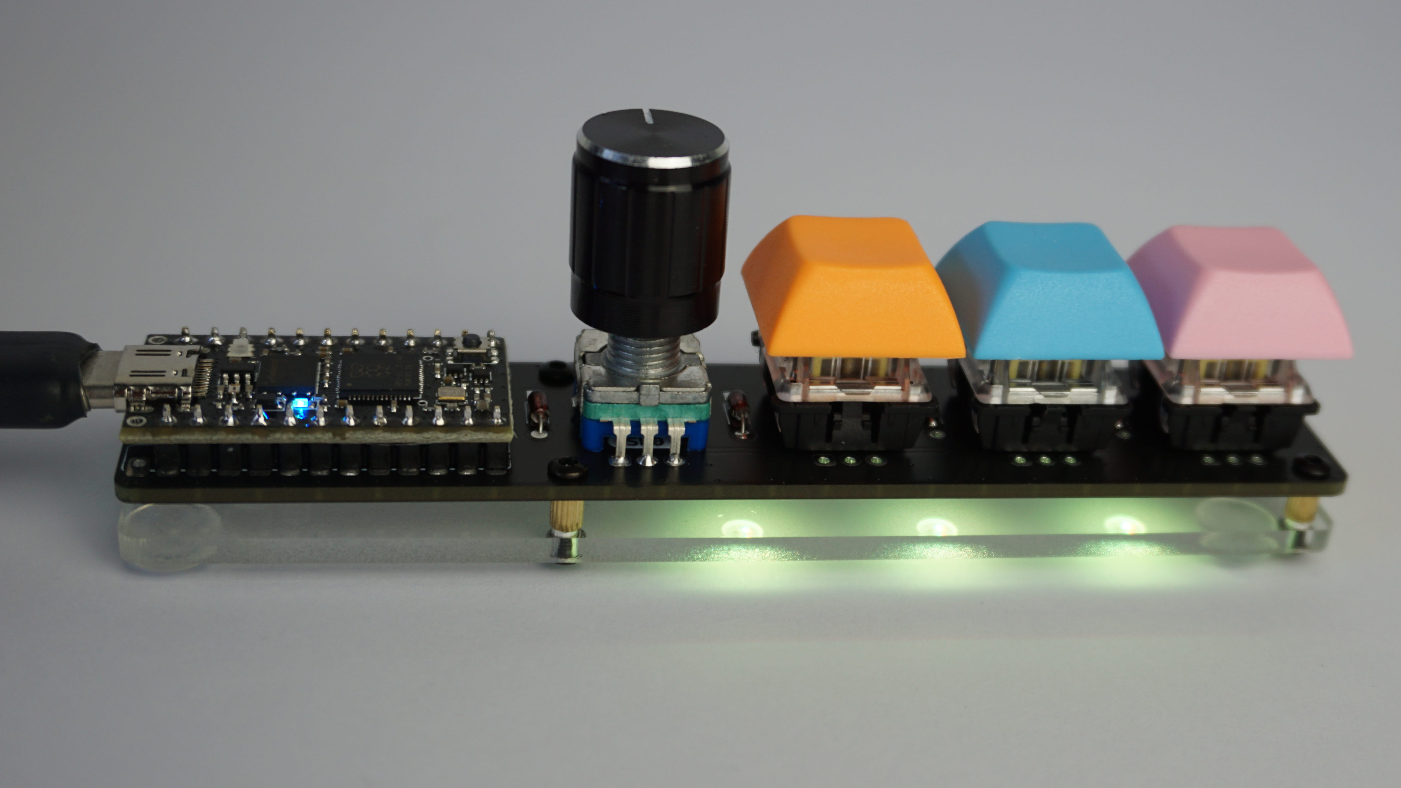
By the end of the workshop you should be walking away with a keyboard consisting off three keys and a rotary encoder, that you can program to perform any task you can imagine. This could span from a simple volume knob, to dedicated copy / paste keys, or even typing the entire bee movie script with one keypress.
Soldering
Required Parts
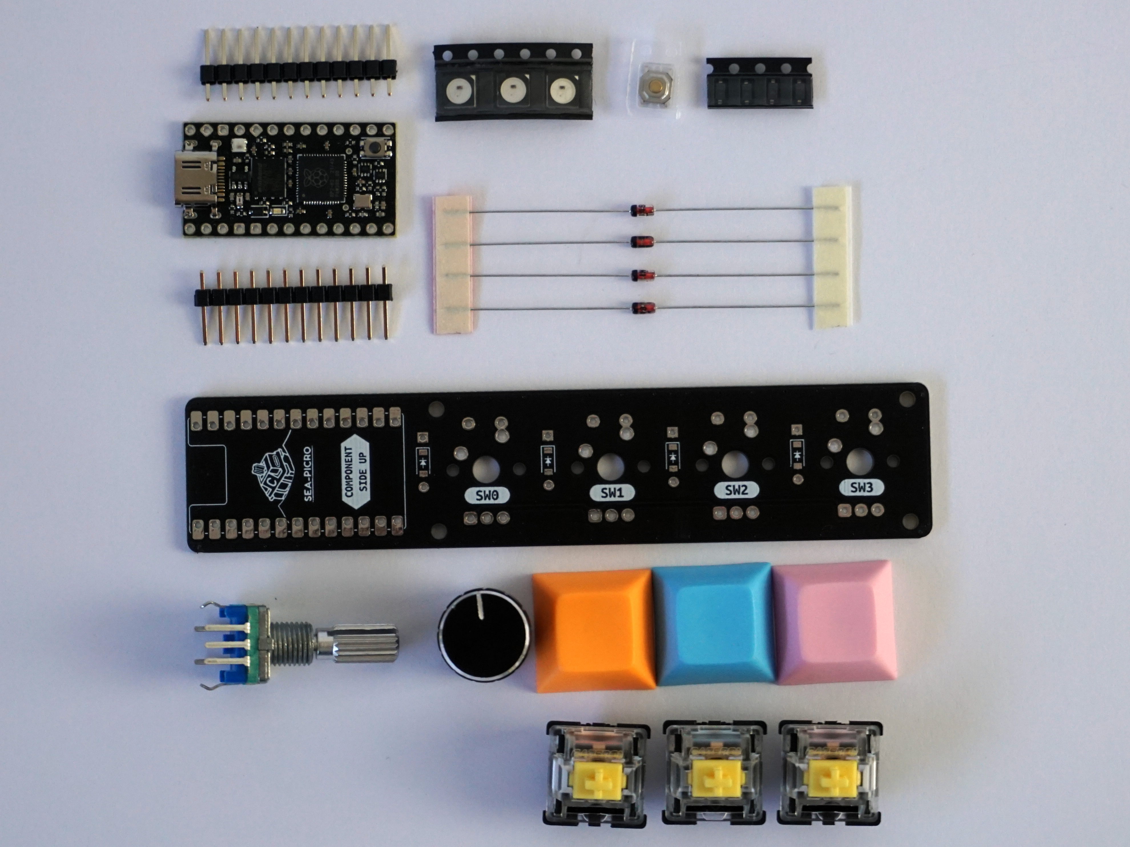
Before starting, ensure you have all the below components on hand.
- 1 x Sea-Picro
- 1 x PCB
- 2 x 12 pin headers
- 4 x Diodes (through hole or surface mount)
- 3 x WS2812B LEDs
- 1 x Reset Button
- 3 x Keyswitches and keycaps
- 1 x Rotary encoder and knob
You will also require the following tools.
- Soldering iron
- Solder
- Tweezers
- Flush cut side cutters
- 1.5mm hex/allen key
Soldering Tips
The most important thing to remember with soldering is that the solder flows to wherever is hot. As such it’s important to heat up the components you are trying to solder before feeding solder into the joint. A rough rule of thumb is to hold your iron against the components for a second before feeding solder into the component being soldered, not the iron. This will ensure the solder sticks to the parts you are trying to attach to the circuit board, and not just pool up on the iron.
Here is a short video showing how to solder, with the first 15 seconds demoing the above instructions.
Diodes
On a normal keyboard, diodes are used to prevent an effect known as “ghosting”, where the microcontroller thinks more keys are pressed than actually are when specific key combinations are pressed. You will see diodes in two different package types, a glass tube with leads (through hole) and a black rectangle with small pads (surface mount). This kit allows you to pick and choose what package you want depending on how challenging you want it to be.
Through Hole Diodes
We first need to bend the leads on the diode to be the same width as the holes in the PCB. 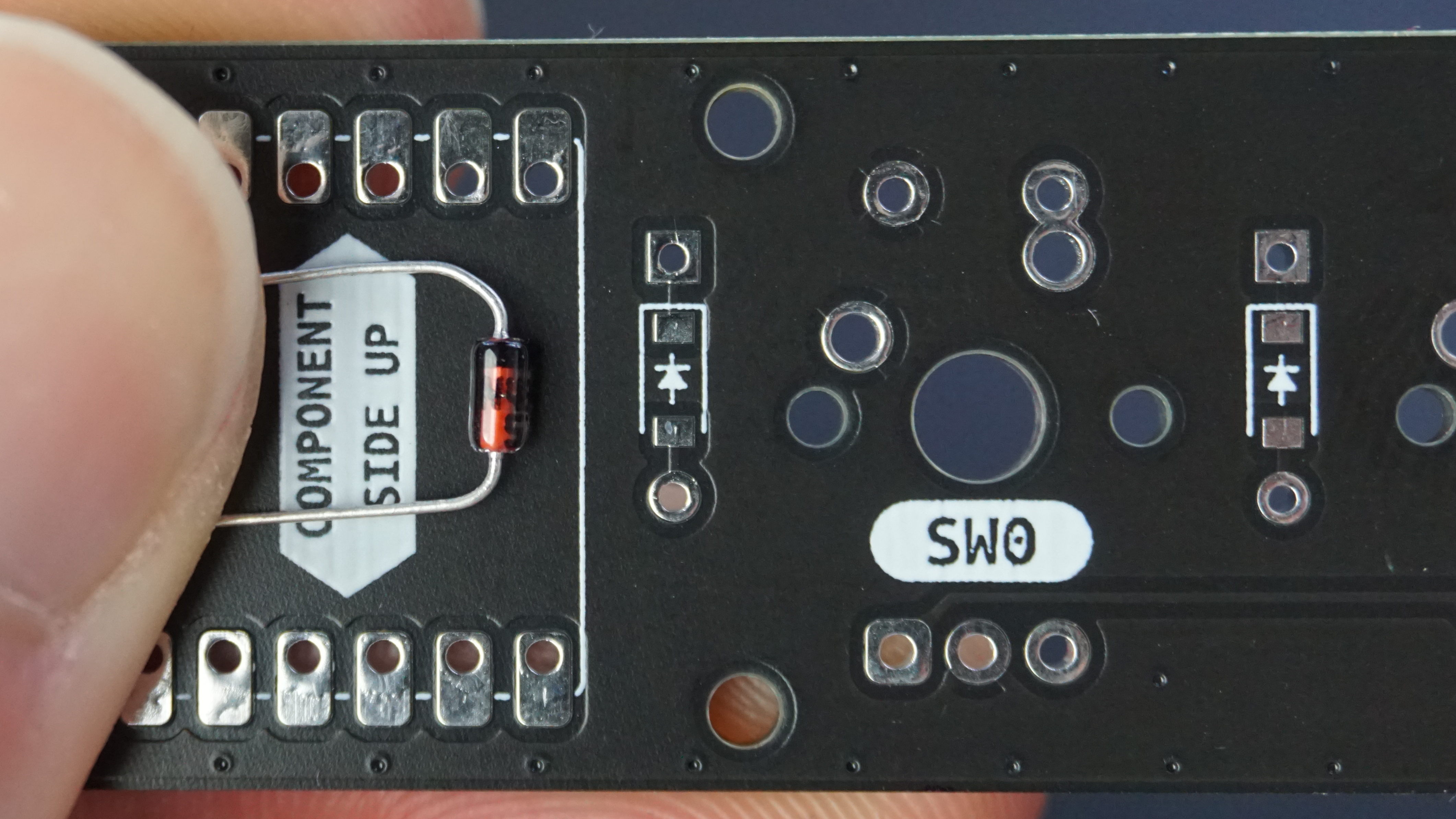
Then insert it, ensuring the black bar on the diode is aligned with the white bar on the PCB. 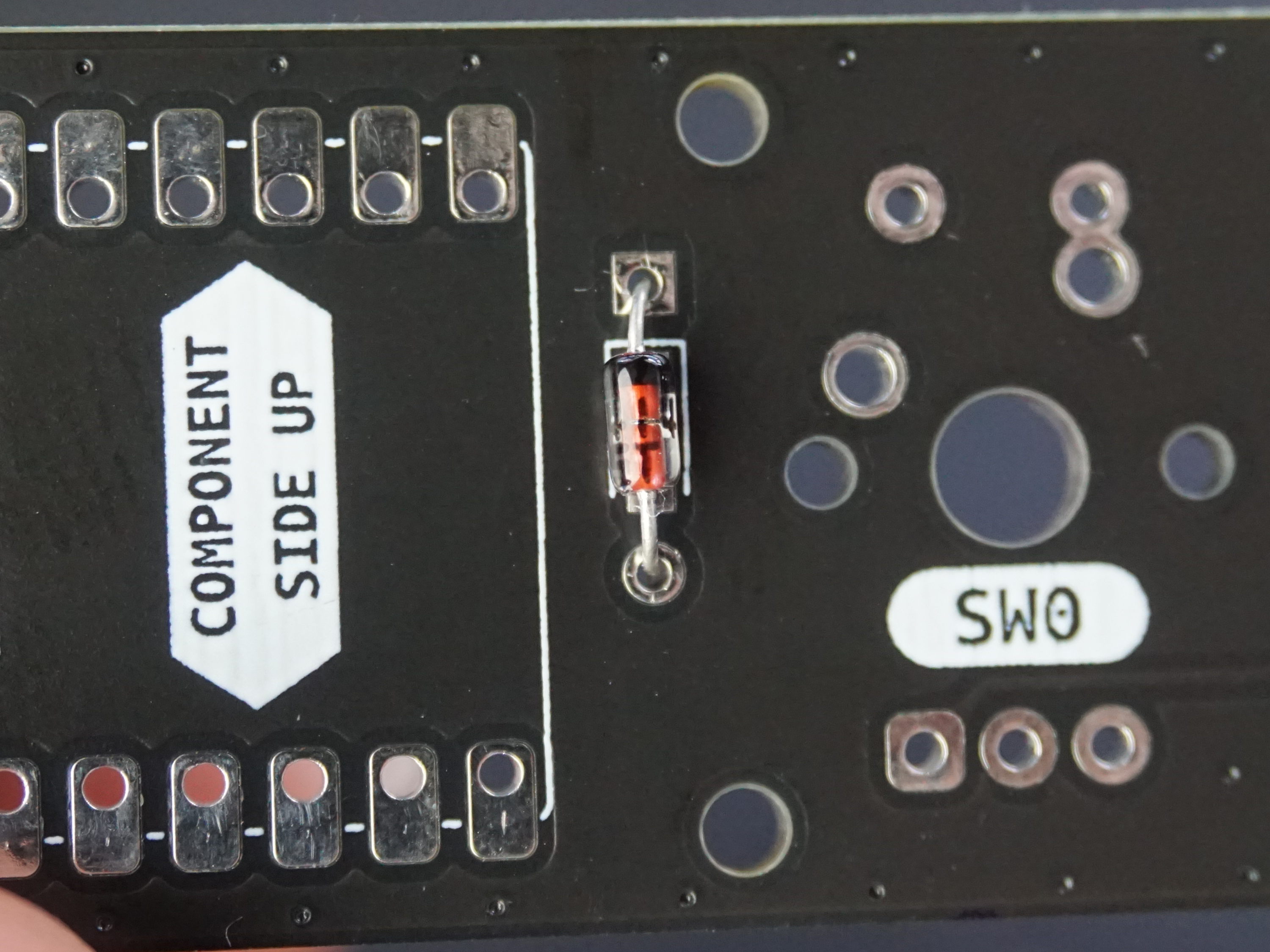
To hold it in place whilst soldering, flip the board over and bend the leads outwards. 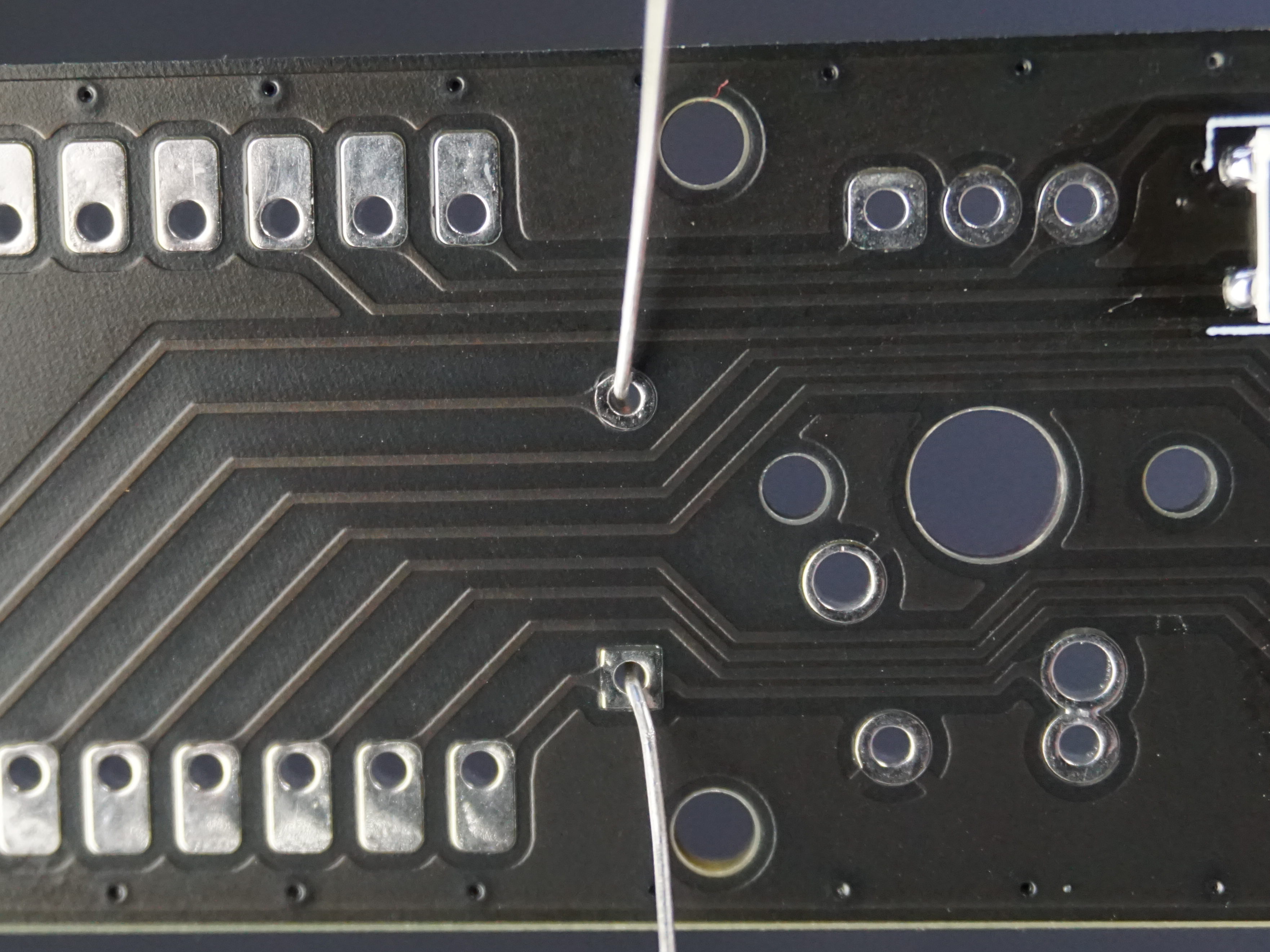
Solder one of the leads. 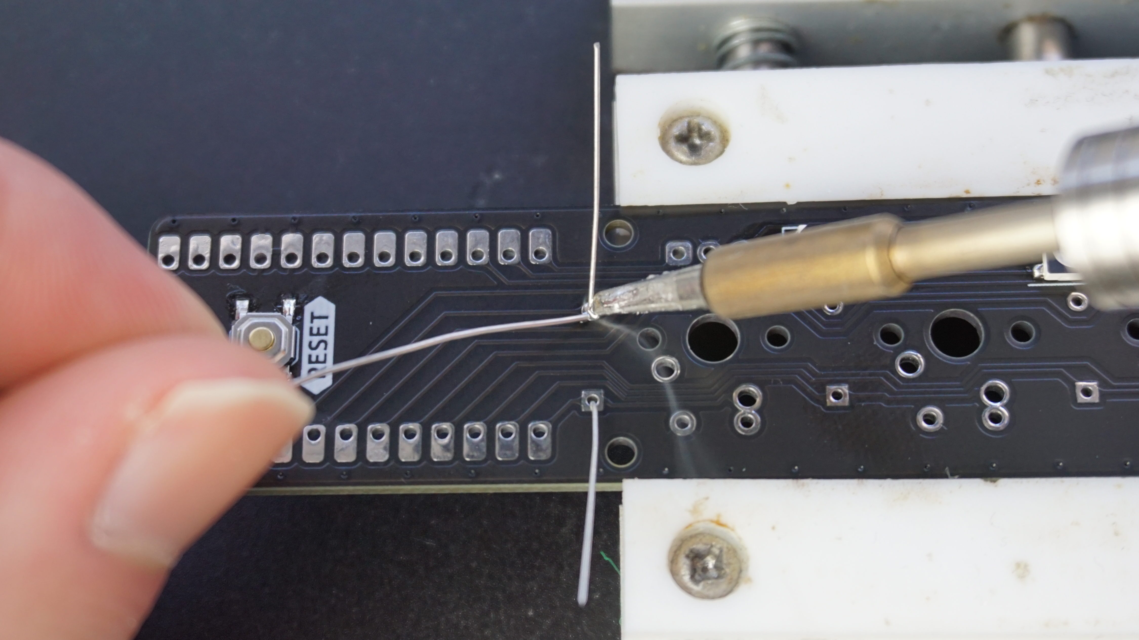
Flip the board back over and check the diode is still flush with the PCB, if not heat up the joint and move into position. 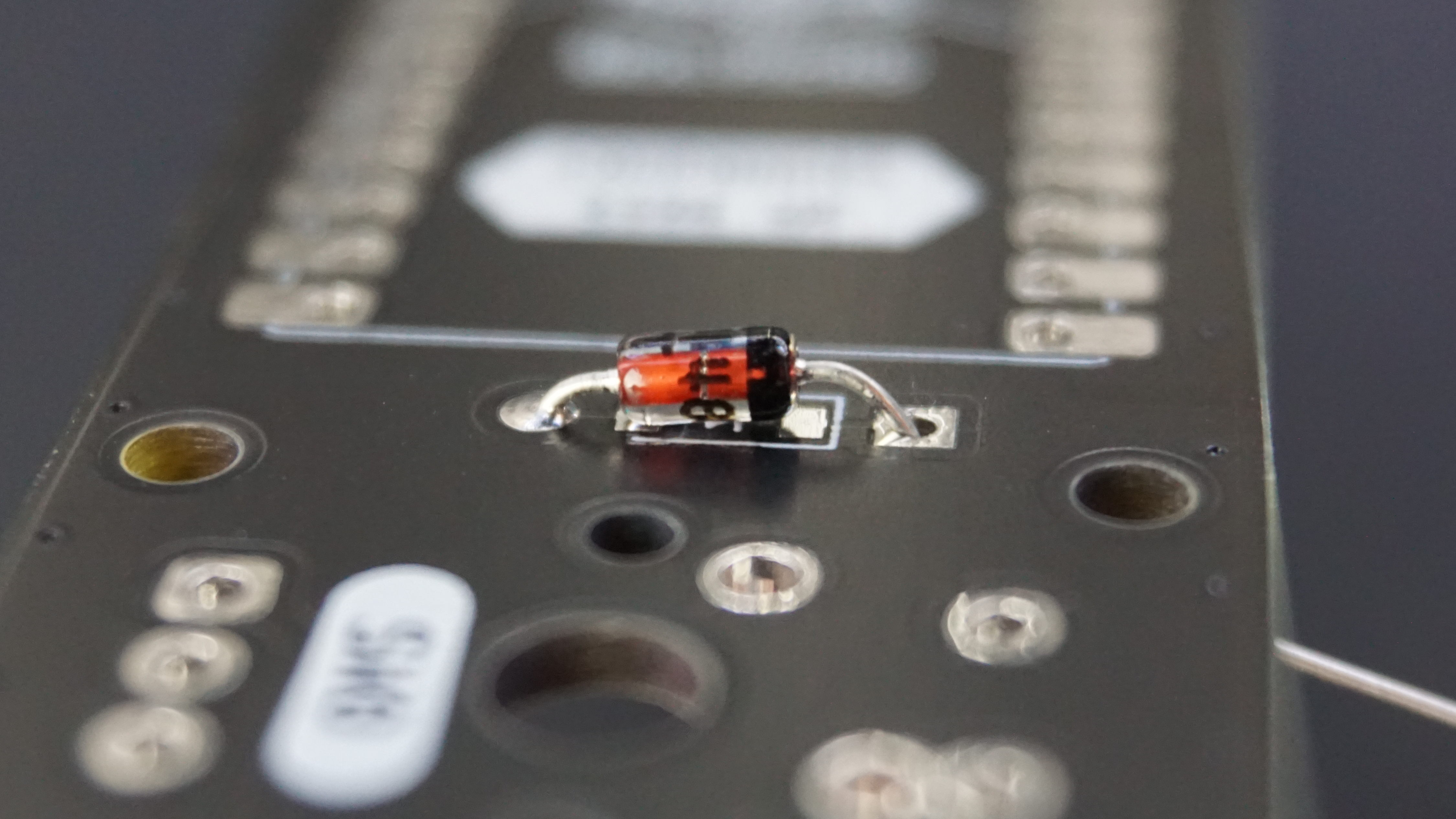
With the diode in place, solder the remaining lead. 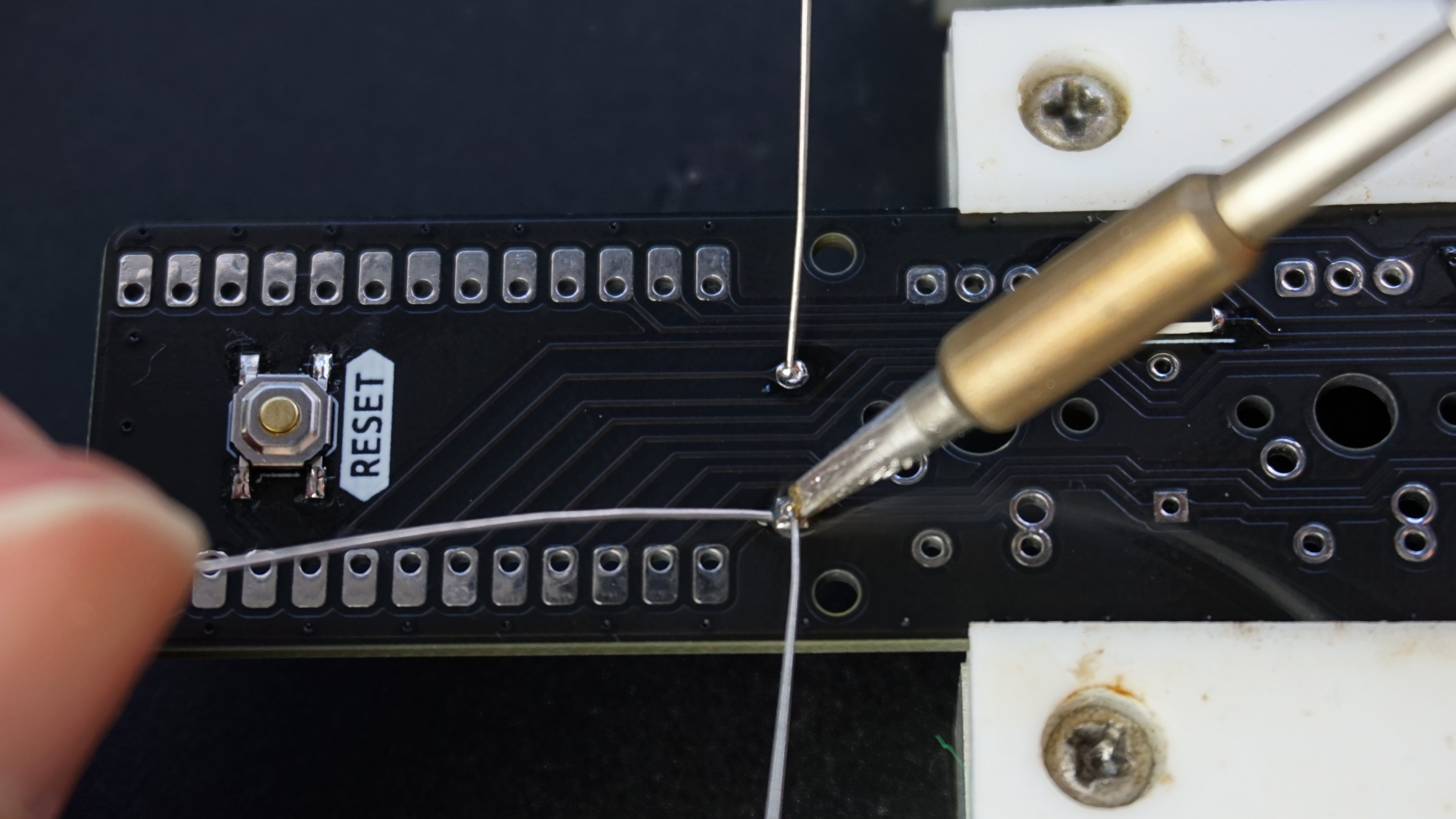
Finally, trim the leads using the flush cut side cutters. 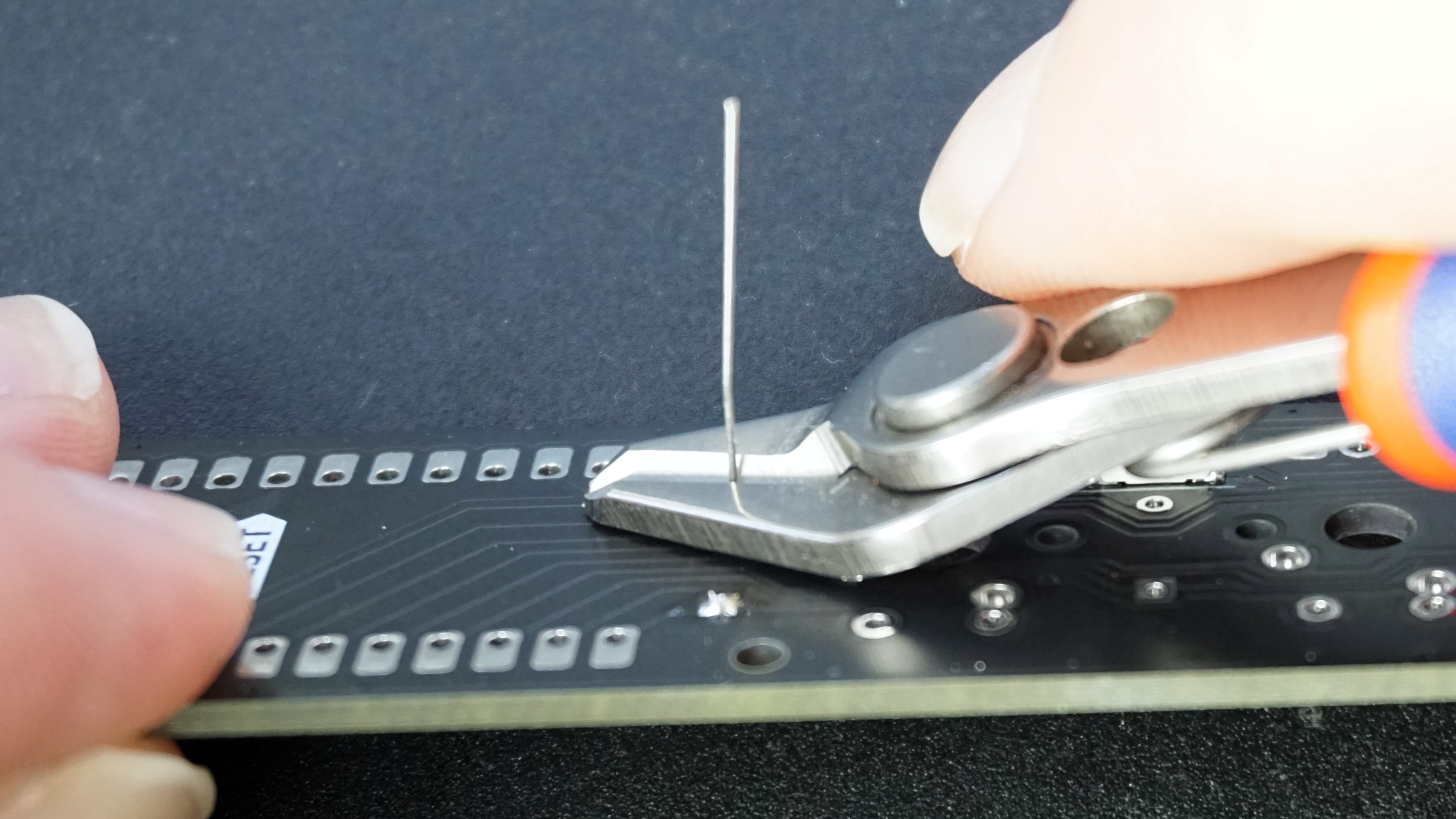
Surface Mount Diodes
Like through hole diodes, surface mount diodes are directional and won’t work if installed backwards. They have a horizonal line on one end of the package which lines up with the line on the PCB. This can sometimes be hard to see, but shining light from the side of the package will help reveal the marking. 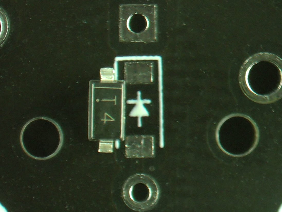
As we have done previously, add solder to one pad. 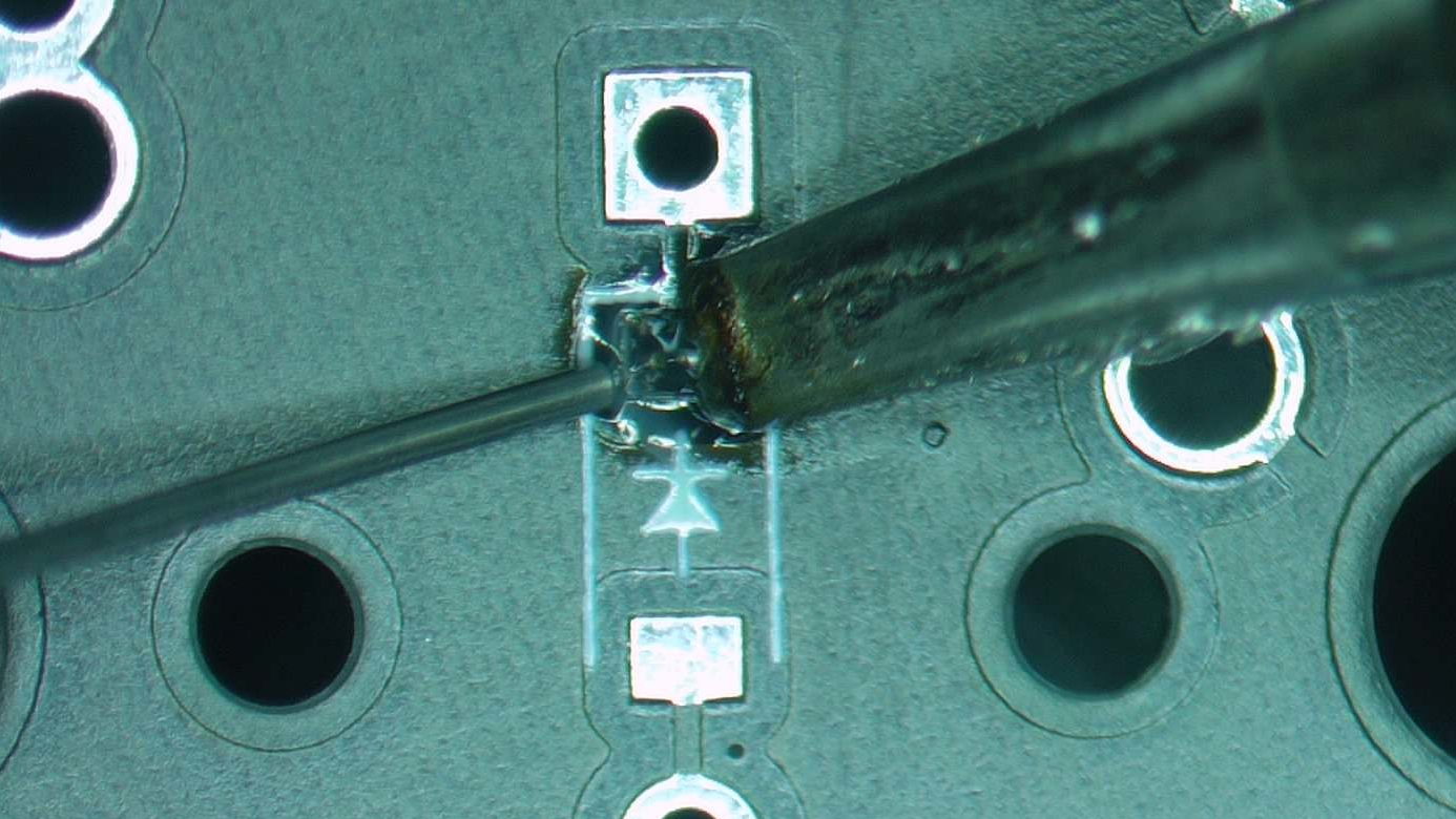
Then ensuring the component is in the correct orientation, tack one pin in place. 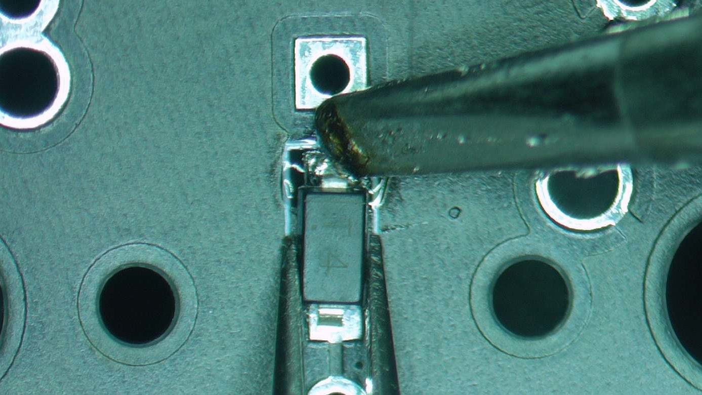
Then solder the reminaing pin in place. 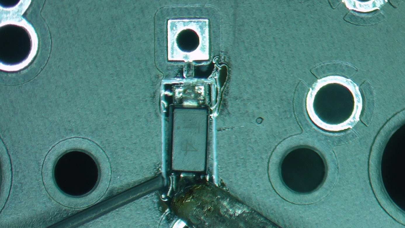
Finish soldering all four diodes, and you’ll have a board that looks like the below. (You can pick and choose through hole vs surface mount depending on how much of a challenge you are seeking.) 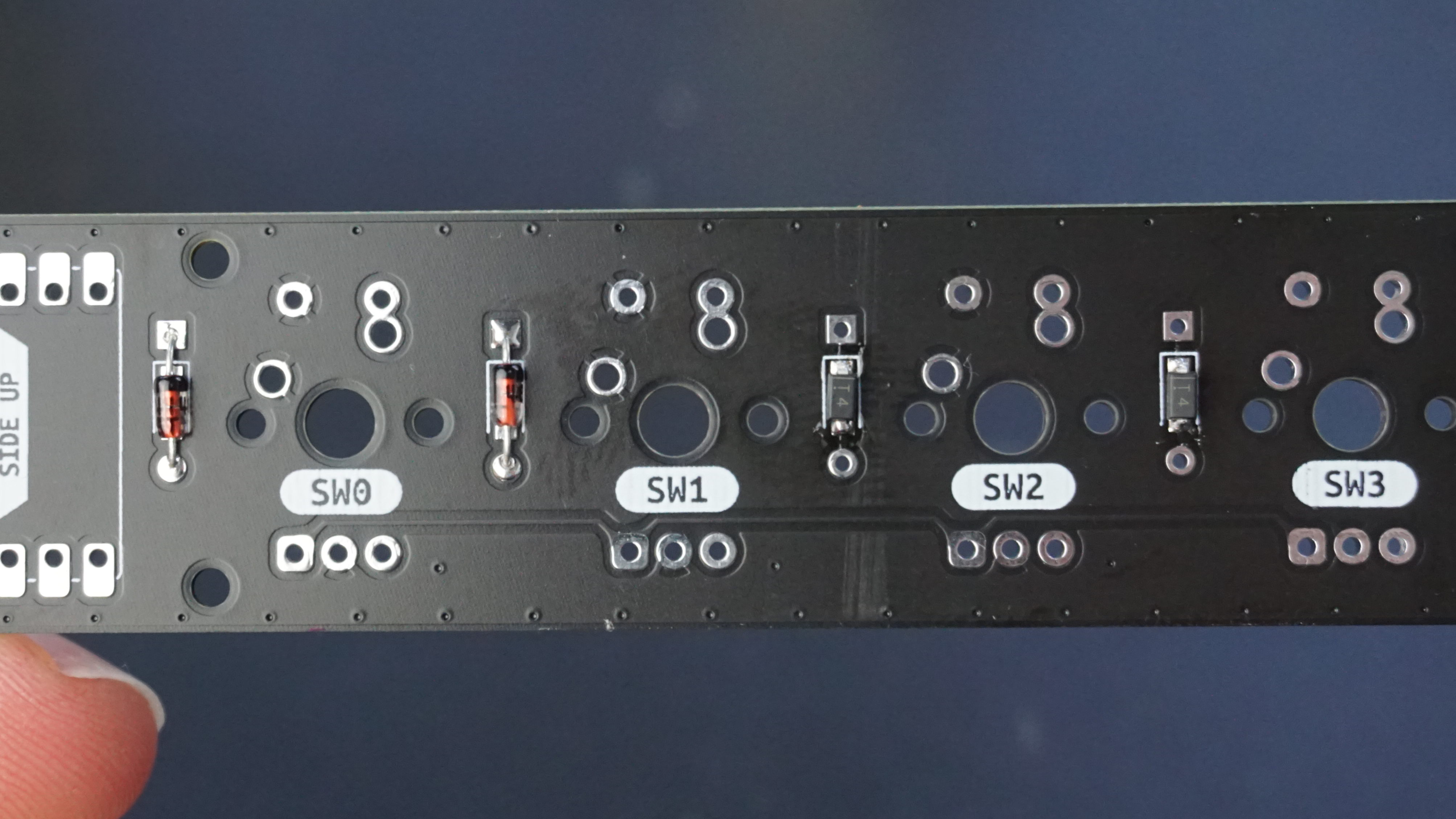
Microcontroller
The microcontroller is the brains of any keyboard, with it scanning for key presses, figuring out what key was pressed, then sending the relavent keypress up to the computer all in a fraction of a second. A RP2040 based board, Sea-Picro, was chosen for this project as it can be programmed in python without installing a toolchain and has good supply even during the chip shortage.
We first need to solder the pin headers to the microcontroller, and can use the PCB to keep the pins aligned as shown below.
The pin header is one pin shorter than the IO on Sea-Picro, please leave the empty pin at the USB connector end as shown in red.
With the pin header in the correct position, tack one pin at each end of the header in place. 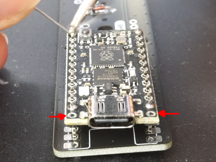
With the headers tacked in place, confirm the pins are square to the microcontroller. If they are not, heat up one of the solder joints, and gently push the connector into alignment. Make sure you don’t touch the pin you are heating up otherwise you’ll burn yourself! 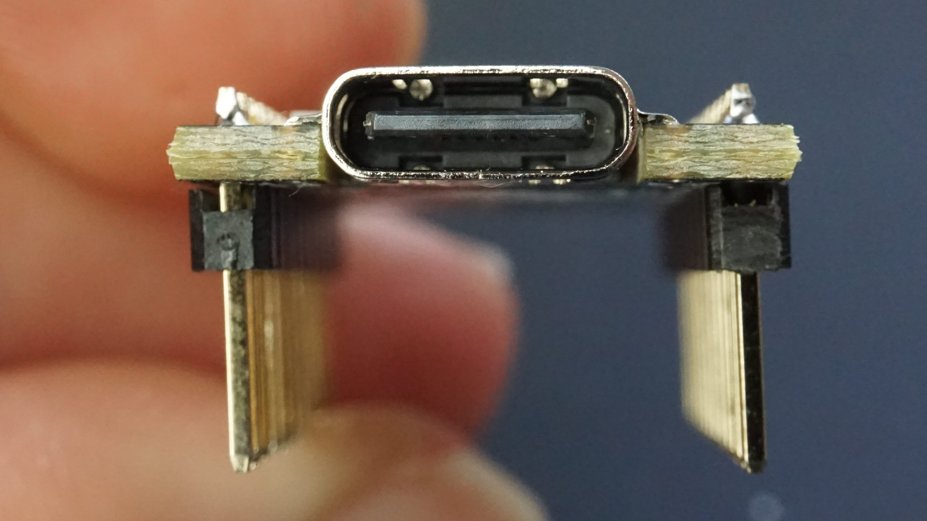
Once the pins are square solder all of the pins. (sorry for the blurry photo) 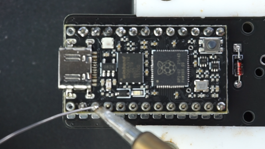
With all the pins soldered on Sea-Picro, ensure it’s placed on the same side as the diodes with the USB connector facing towards the edge of PCB as per the above photo.
ENSURE THIS IS CORRECT OTHERWISE YOUR BOARD WILL NOT WORK.
With Sea-Picro oriented correctly, flip the board upside down and tack two opposing corners in place on the PCB. 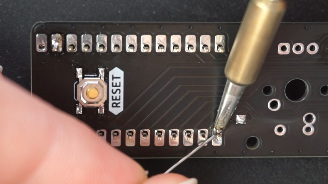
If Sea-Picro isn’t sitting flush to the PCB, heat up a pin and adjust as necessary. 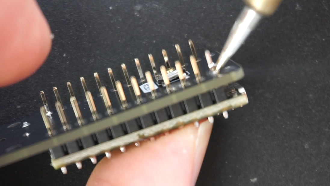
With the microcontroller sitting flush to the PCB, solder the remaining pins. (forgot to photograph this step)
With all the pins soldered, snip off the legs so they don’t stick out. I’d recommend cutting the leads towards the desk so they don’t go flying around the room. 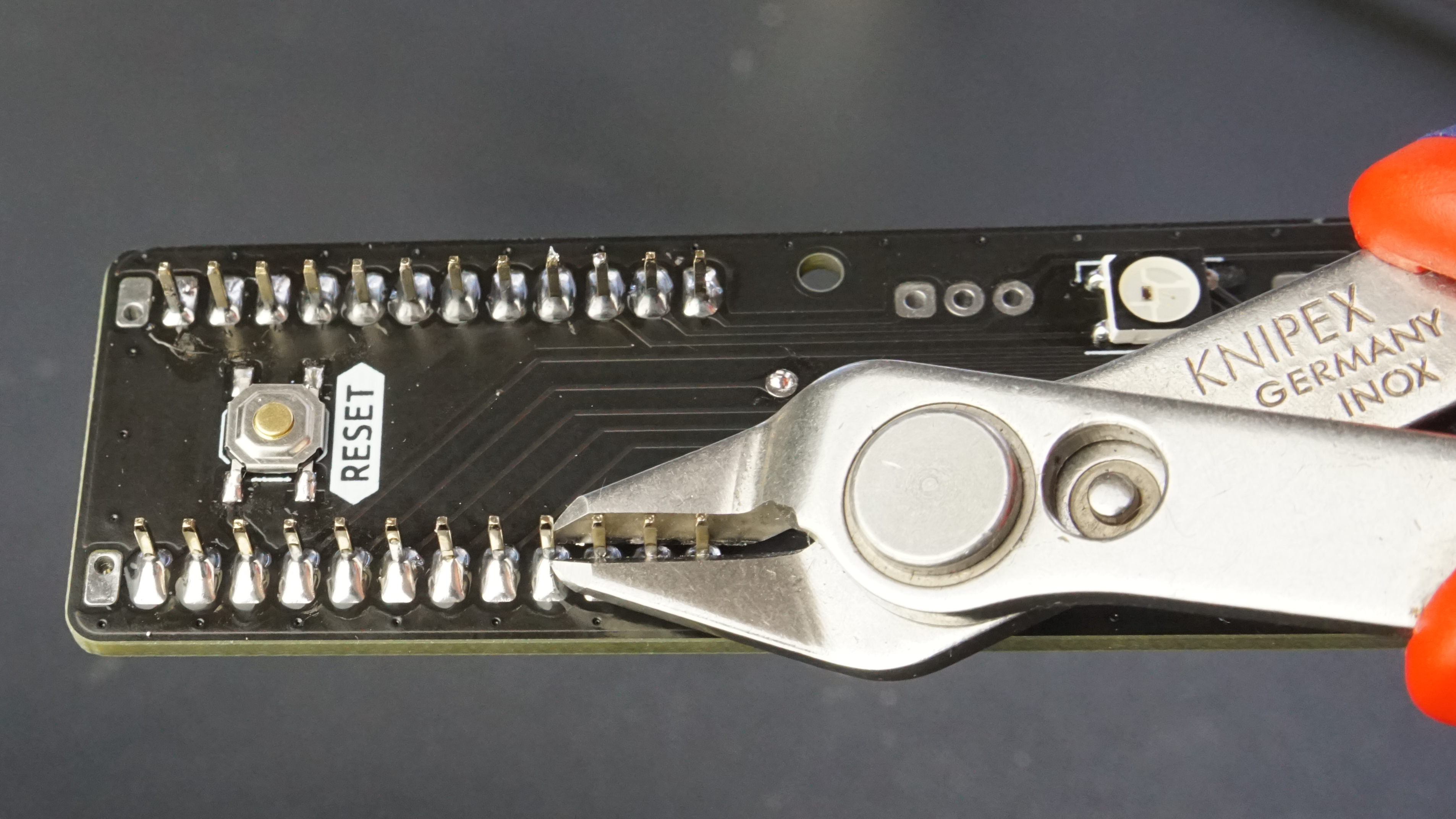
Reset Switch
Next we will solder the reset switch, which is commonly used to put the board into bootloader mode so you can flash different firmware / keymaps to the microcontroller. The board we are using (Sea-Picro) already has a reset button on it so this step is not required, but is good practice none the less.
Place the PCB into the 3d printed soldering jig upside down. This was a last minute addition to the workshop so please excuse the bare PCB in the photo. 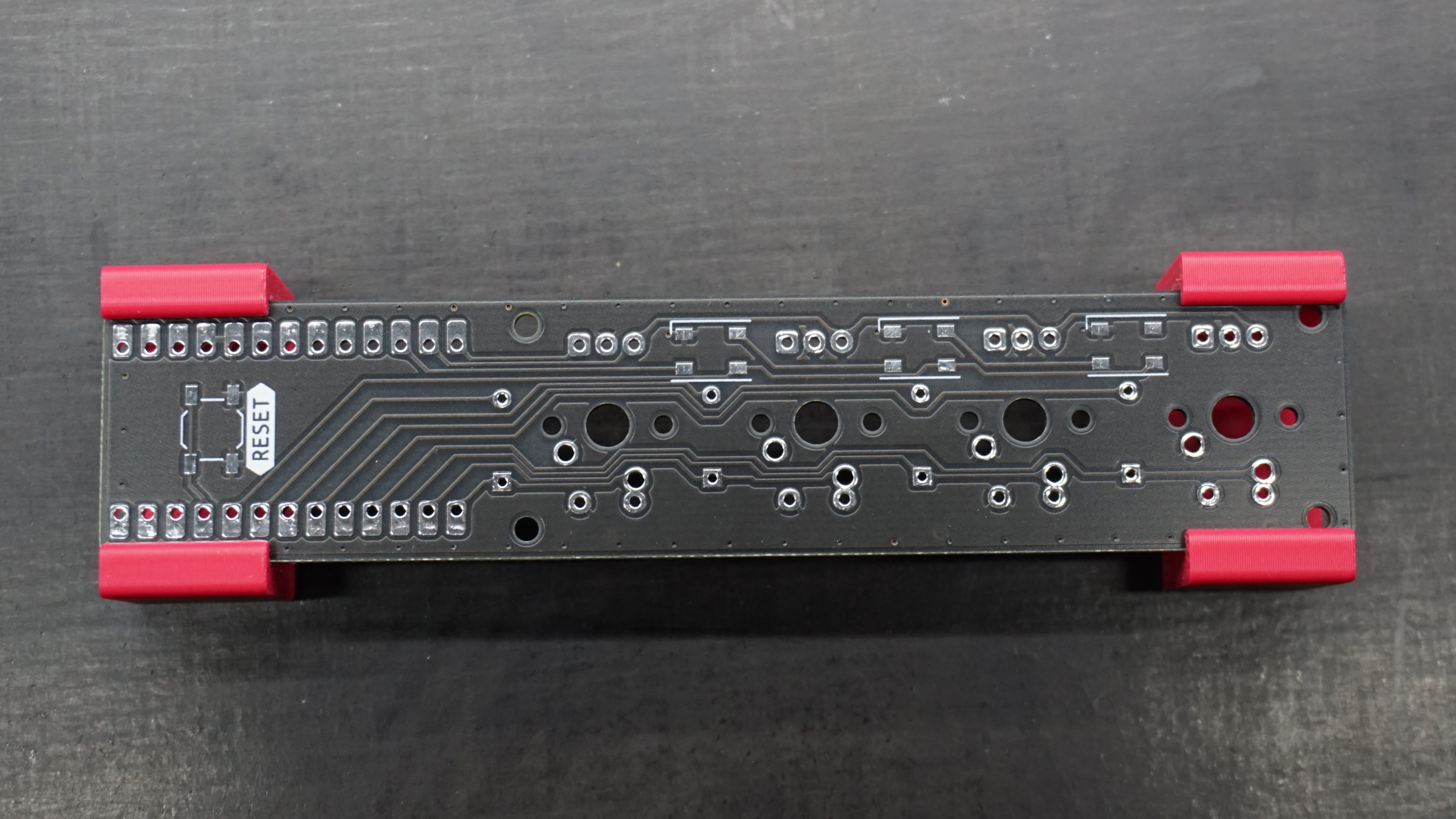
First, put a small amount of solder onto one of the pads. 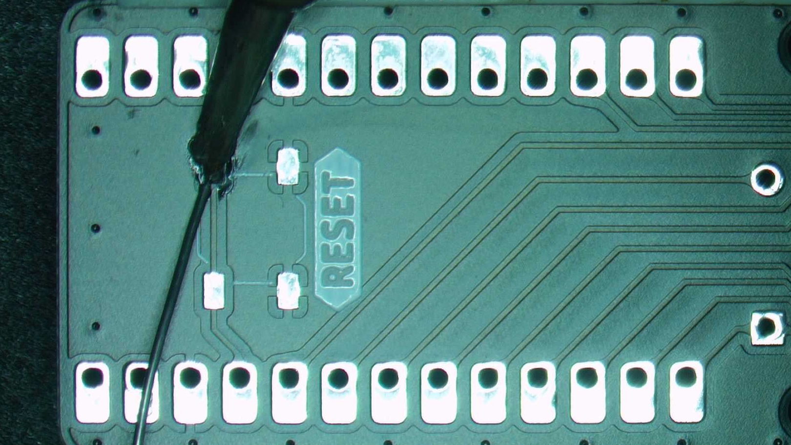
Then using tweezers, place the reset switch in position and melt the solder you previously placed down to tack the reset switch in place. 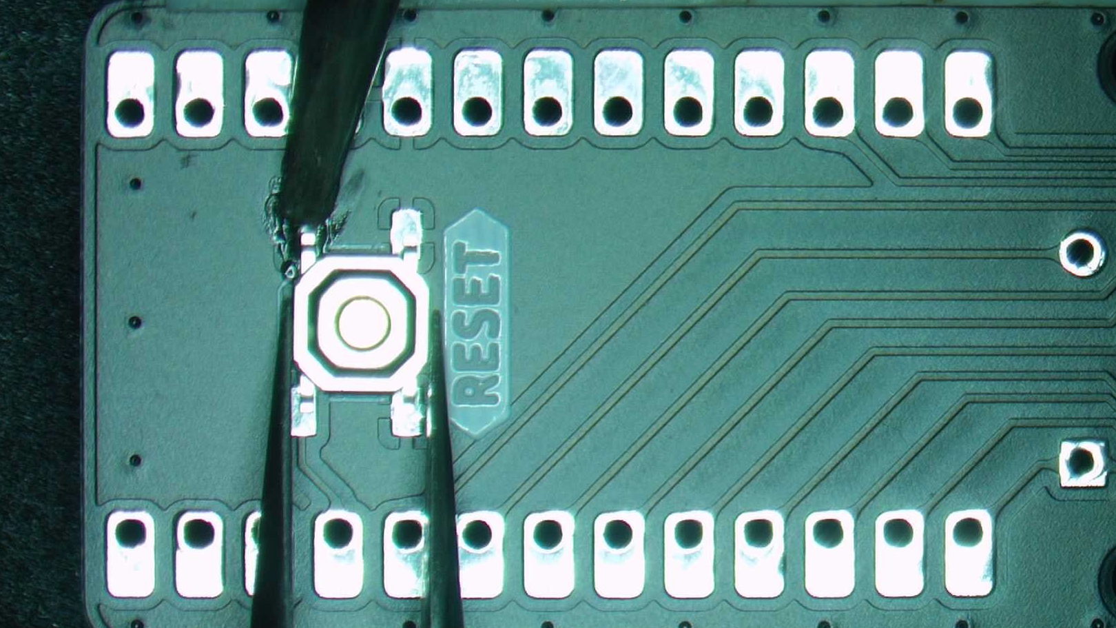
Add solder to the remaining pins to secure the reset switch in place. 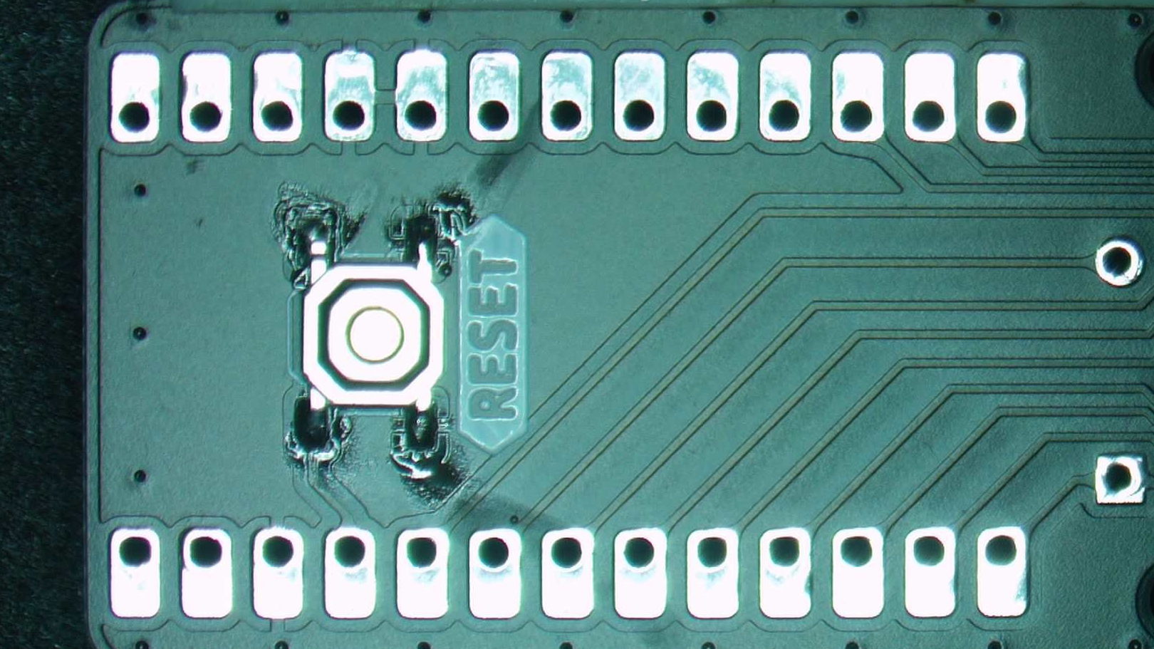
LEDs
Adding LEDs to your board is a simple way of adding some colour to your desk, but it can also be used to identify the state of your keyboard, e.g. if it’s setup for macros or volume control. The LEDs used are known as “addressable LEDs” in that you send a serial sting of data to the LEDs to set their colour. Due to the packaging of addressable LEDs they can be a bit challenging to solder, so don’t hesitate to ask for help.
Similarly to the reset switch, tin one pad of the LED footprint. 
Line up the white triangular marking in the corner of the LED with the “L” shaped corner of the marking on the PCB. This is crucial otherwise your board won’t work. 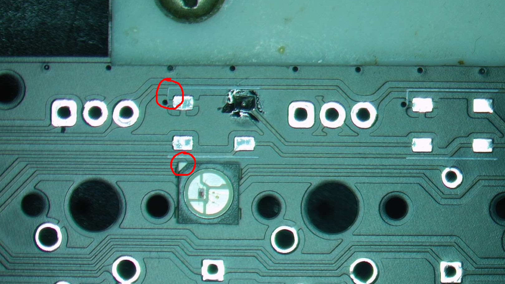
As with the reset switch, heat up the previously placed solder and tack the LED in place. 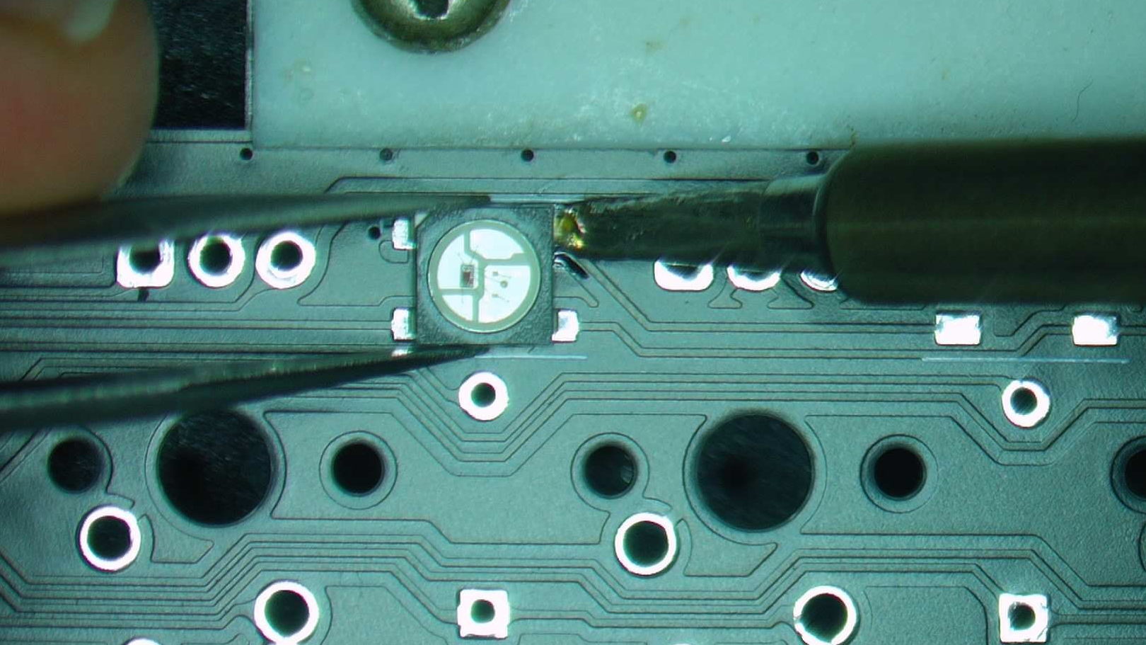
Then solder the remaining pins. You may find the pad with the “L” shaped marking more challenging to solder, and this is due to it being the ground plane which has a large thermal mass. If you get a blob of solder stuck to the LED like below, ensure you hold the iron to the PCB for a few seconds to heat it up before adding solder. 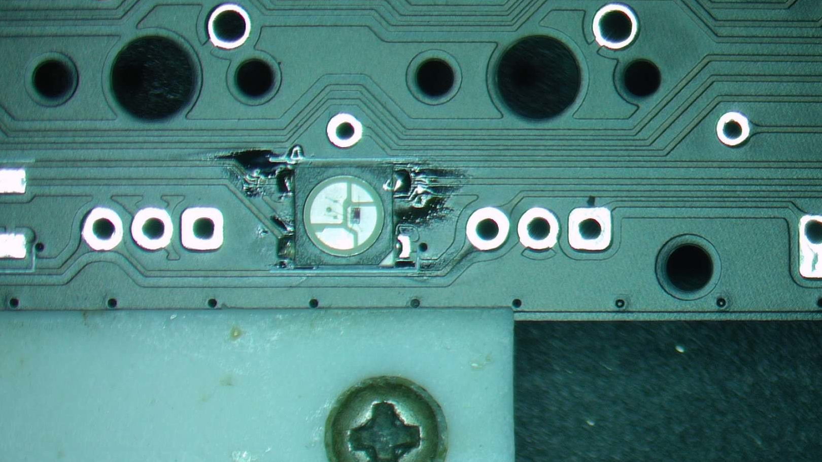
Here is a video showing the entire process.
Once you’ve soldered the first LED, continue doing the other two on the board until they are complete. 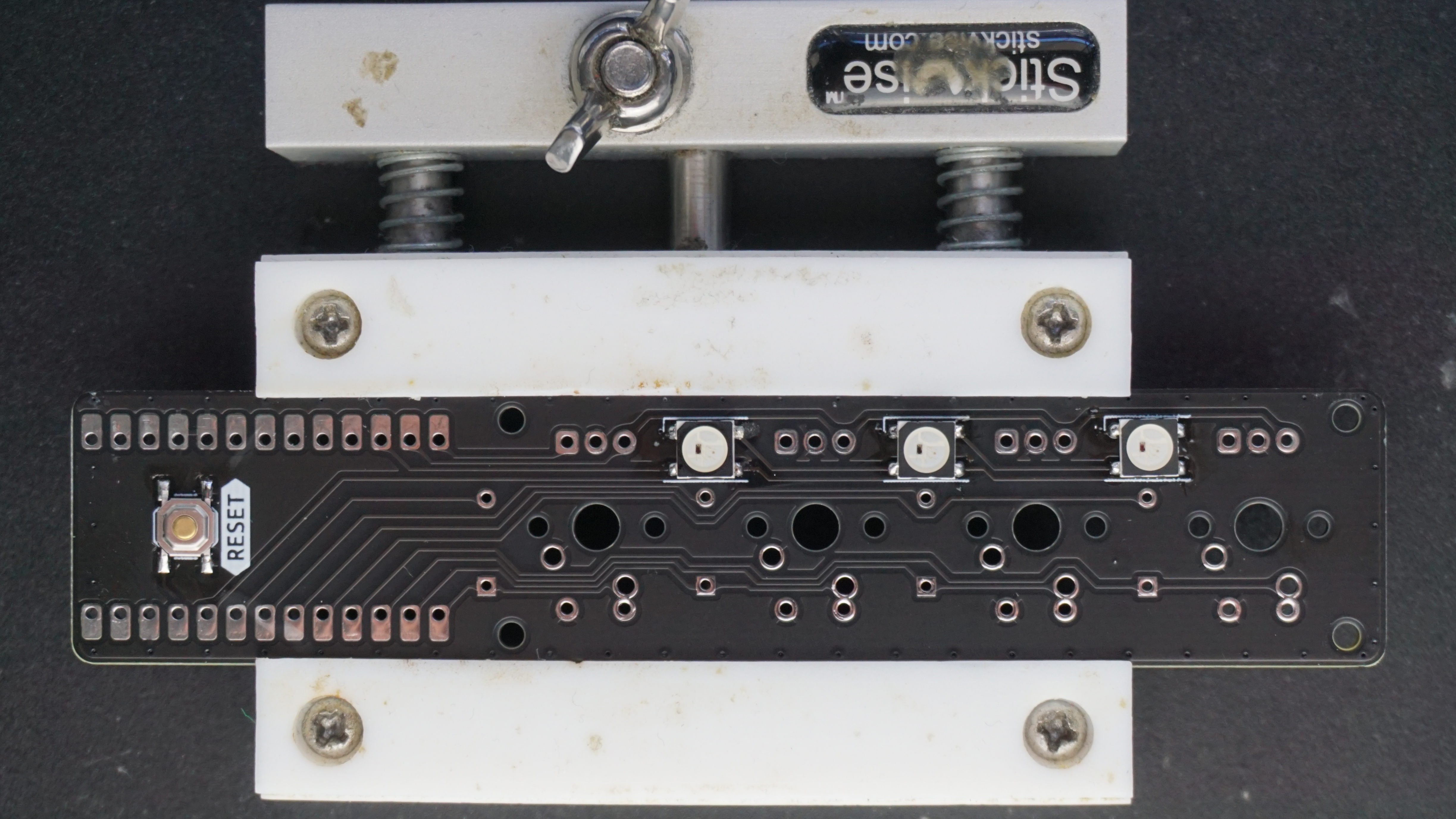
Switches
Switches are arguably the most important part of a keyboard, as without them you wouldn’t be able to type anything! They come in a variety of options with different force profiles, but regardless of what switch you pick the install process is the same.
First, grab a switch and place it in the position you want. Remember we are fitting a rotary encoder as well so consider where you want that to live as it’s much taller than a switch. In this case, I’m installing switches in 1,2,3, and an encoder in 0. 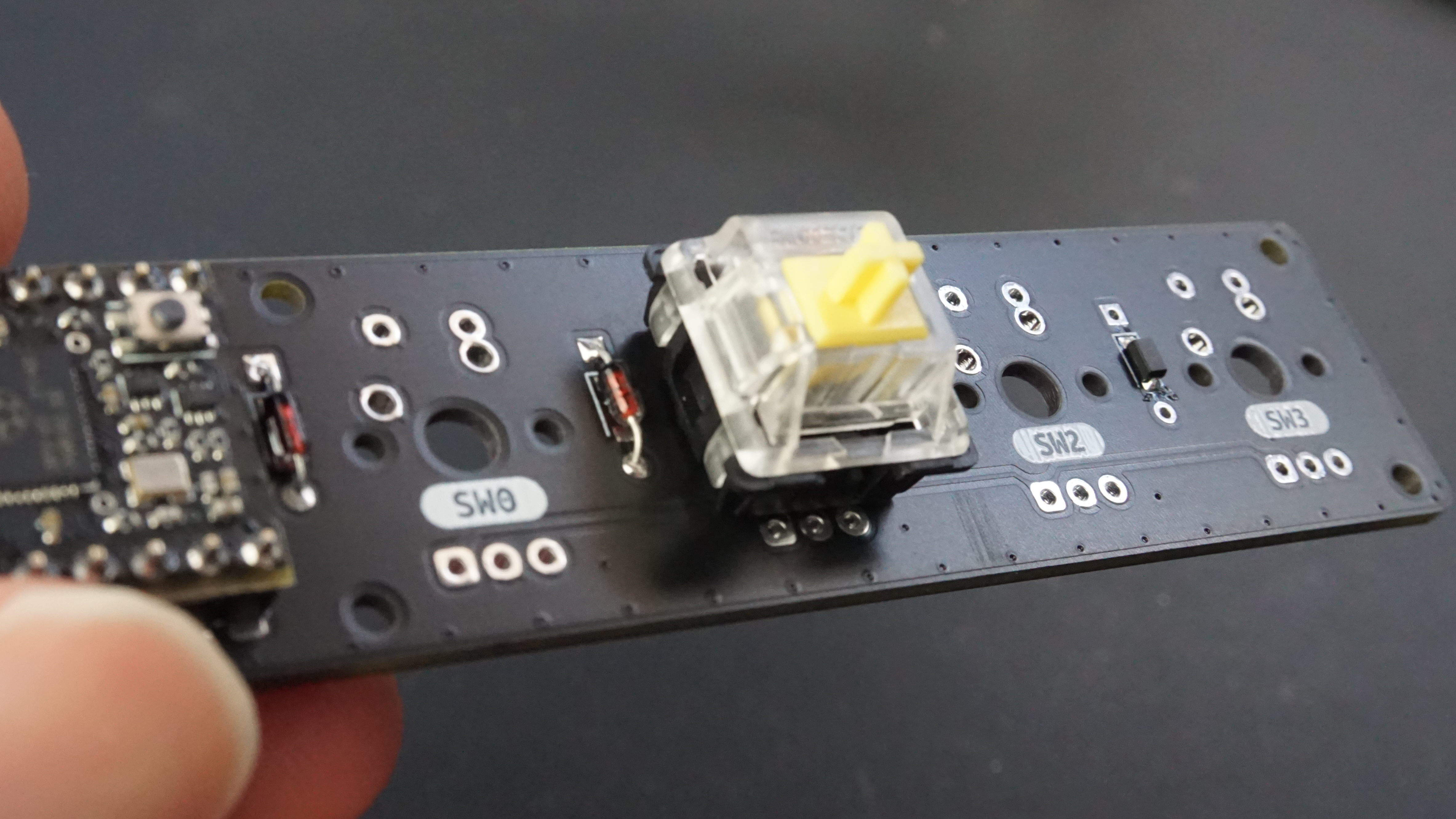
With the switch pressed into place, flip the board over and solder the pins in. Repeat for the other two switches. 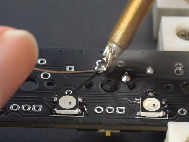
Encoders
In addition to the push button/switch in the encoder that shorts two pins when pressed, the encoder has two additional outputs that go high / low as the knob is turned, sending the direction of rotation to the microcontroller. As such you can turn the encoder for as many revolutions as you’d like, so they are a great way to control continuous values such as volume or opacity.
The first step is to snip both mounting legs off the encoder with the side cutters. 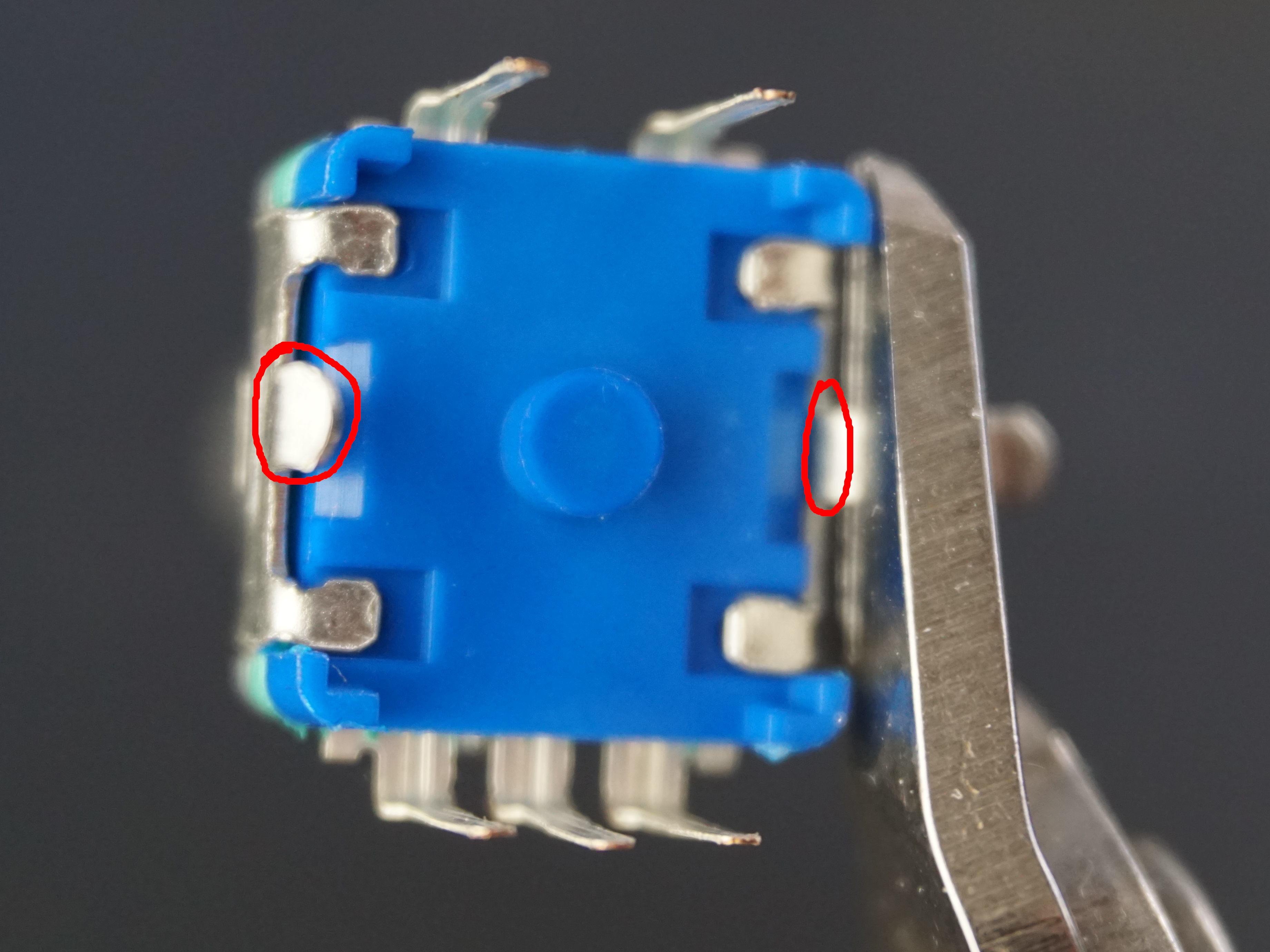
With the legs removed, insert the encoder into the PCB and tack opposing pins in place. Don’t solder all the pins yet. 
With the pins tacked into place, ensure the encoder is sitting flush / square on the board, and adjust as necessary. When square, solder the remaining pins. 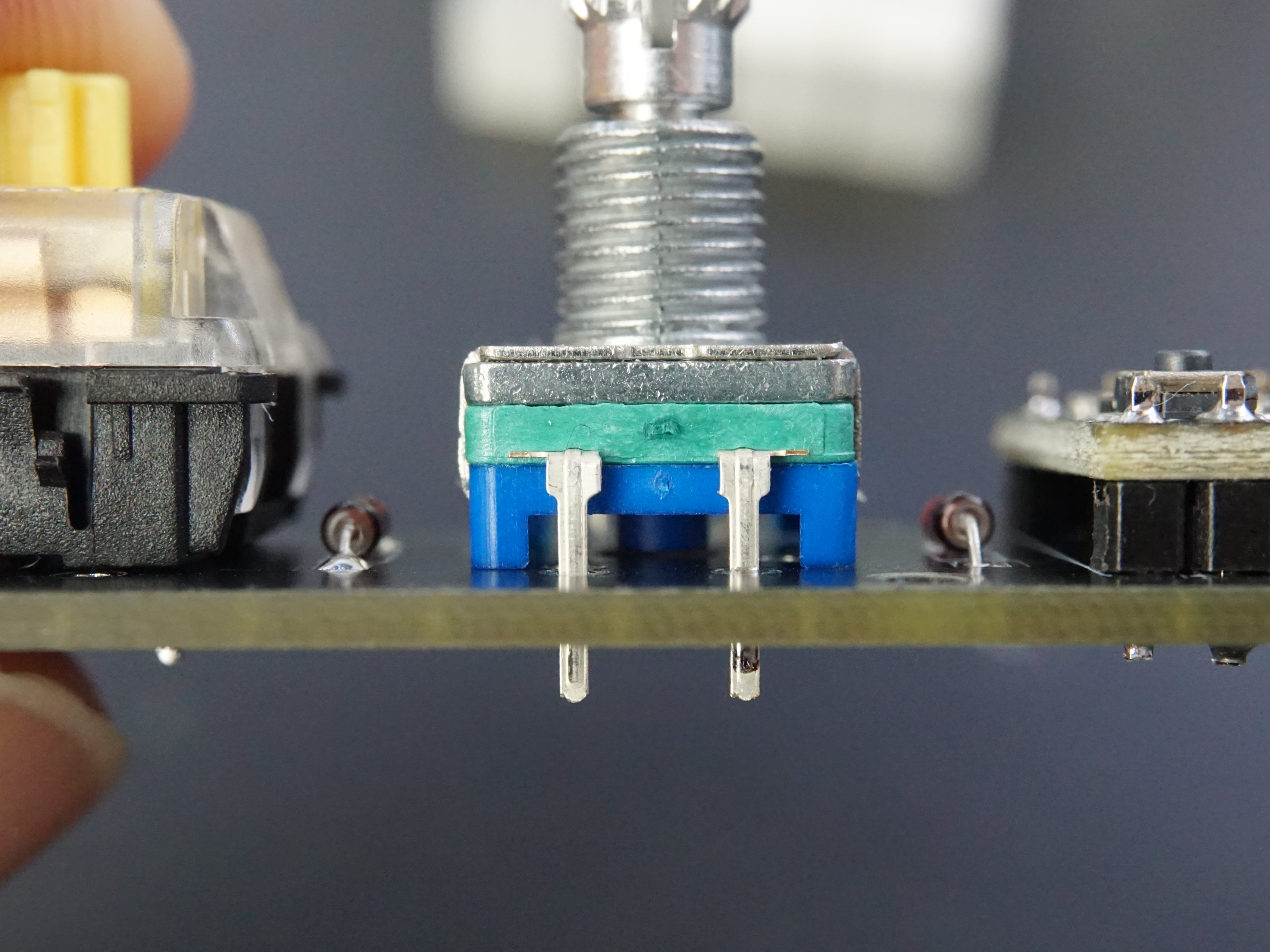
With all of the encoder pins soldered, install the keycaps and knob, and celebrate finishing the soldering of your new keyboard! 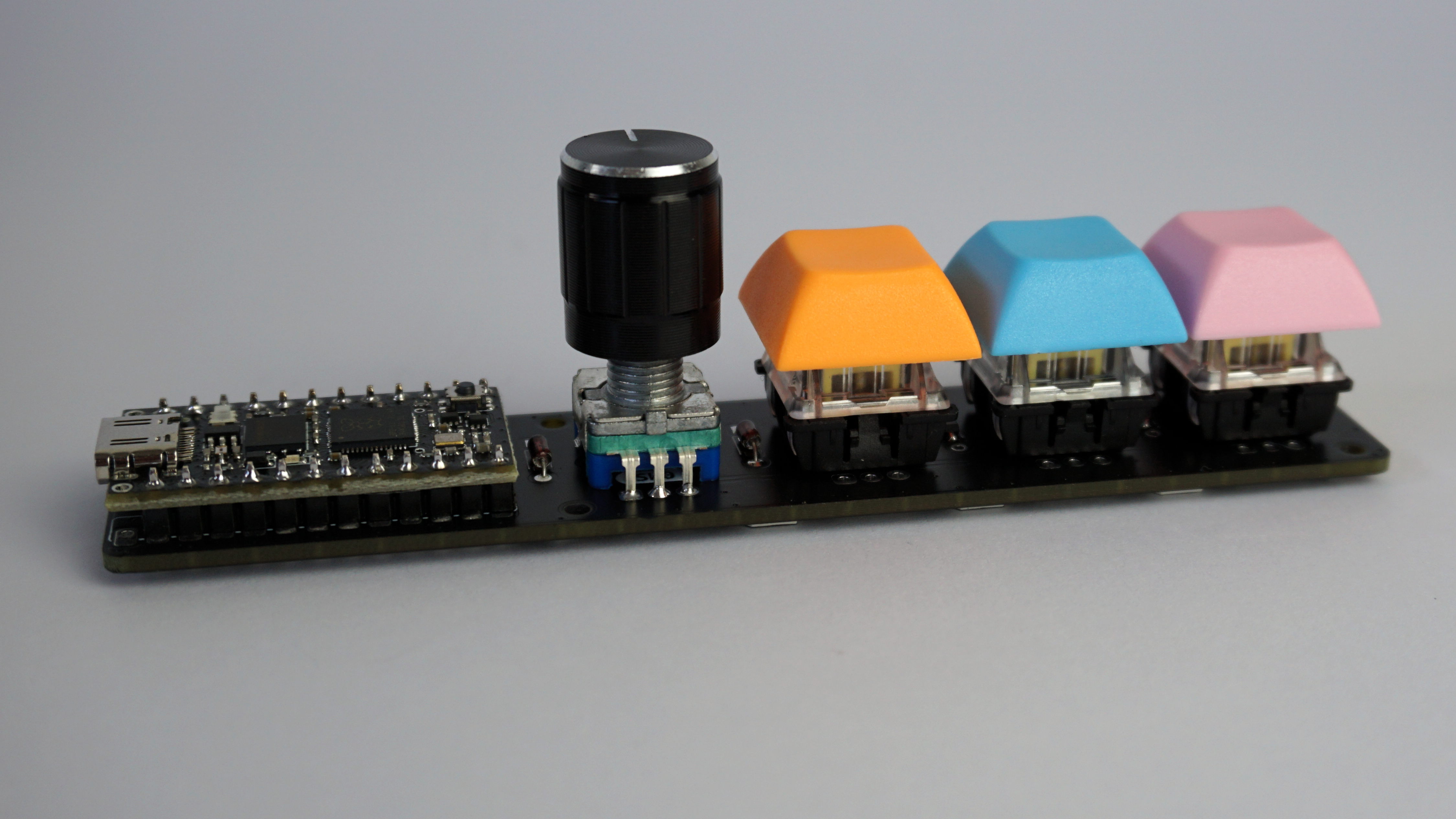
Firmware Configuration
Out of the box, Sea-Picro (and the RP2040 microcontroller within) has no idea what it’s purpose in life is, so we need to configure it to not only be a keyboard, but one which works with our custom made PCB, and your custom keycodes. To do this, we will be using KMK, a CircuitPython based keyboard firmware framework, due to it’s ease of programming - all you need to do it edit a text file and when you save the code it will run.
Sea-Picro comes flashed with CircuitPython out of the box, but we need to load KMK and the code.py file with our keyboard configuration. The steps are below:
- Download a copy of KMK.
- Unzip it and copy the KMK folder and the
boot.pyfile at the root of the USB drive corresponding to your board (often appearing as CIRCUITPY). - Unplug and replug your device to force the
boot.pychanges to be implemented. - Open the existing
code.pyfile on the CIRCUITPY drive with a text editor and replace it with the below code.
1
2
3
4
5
6
7
8
9
10
11
12
13
14
15
16
17
18
19
20
21
22
23
24
25
26
27
28
29
30
31
32
33
34
35
36
37
38
39
40
41
42
43
44
45
46
47
48
49
50
51
52
53
54
55
56
57
# Sea-Picro pinout
import board

# KMK drivers
from kmk.kmk_keyboard import KMKKeyboard
from kmk.scanners.keypad import KeysScanner
from kmk.modules.encoder import EncoderHandler
from kmk.extensions.RGB import RGB, AnimationModes

# Different keycodes that can be sent
from kmk.keys import KC
from kmk.extensions.media_keys import MediaKeys
from kmk.handlers.sequences import send_string
from kmk.handlers.sequences import unicode_string_sequence

# Init keyboard
keyboard = KMKKeyboard()

# Mapping IO pin to position in matrix
# Comment lines in / out depending if you are using diodes or not
# keyboard.matrix = KeysScanner([board.D21, board.D23, board.D20, board.D22,]) # Without diodes
keyboard.matrix = KeysScanner([board.D29, board.D28, board.D27, board.D26,]) # With diodes

# Add encoders, RGB, and media key support to keyboard
encoder_handler = EncoderHandler()
rgb_ext = RGB(pixel_pin=board.D7, num_pixels=3, val_limit=255, val_default=64, animation_mode=AnimationModes.RAINBOW,)
media_keys = MediaKeys()
keyboard.modules = [encoder_handler, media_keys, rgb_ext]

# Configure encoder pins
# As the encoder can be placed in multiple spots we don't define which IO the
# push button is mapped to, and instead leave that for the switch matrix definition
encoder_handler.pins = ((board.D9, board.D8, None, False),)

# Examples of different keys that can be sent
# All valid keys: https://github.com/KMKfw/kmk_firmware/blob/master/docs/keycodes.md#keys-overview
# Strings: https://github.com/KMKfw/kmk_firmware/blob/master/docs/sequences.md#sending-strings
EG_STRING = send_string("I'd just like to interject for a moment. What you're referring to as Linux, is in fact, GNU/Linux, or as I've recently taken to calling it, GNU plus Linux.")
# Unicode (requires config on your PC first) https://github.com/KMKfw/kmk_firmware/blob/master/docs/sequences.md#unicode
EG_FLIP = unicode_string_sequence('(ノಠ痊ಠ)ノ彡┻━┻')
# Chains of key presses
EG_COPY = KC.LCTL(KC.C)
EG_PASTE = KC.LCTL(KC.V)

# This is where we control what keys are sent when a switch is pressed
keyboard.keymap = [
    [
        KC.MPLY, EG_COPY, EG_PASTE, EG_STRING
    ]
]

# Below configures what happens when the encoder is turned
encoder_handler.map = (((KC.VOLD, KC.VOLU, None),),)

# With everything configured, time to become a keyboard!
if __name__ == '__main__':
    keyboard.go()
Press the keys / turn the encoder on your keyboard and see if they all work. By default they will work as below.
- SW0 / Encoder: Media Play / Pause
- SW1: Copy
- SW2: Paste
- SW3: Prints the Linux Copypasta
- Encoder Clockwise: Volume Up
- Encoder Anticlockwise: Volume Down
If you have issues, check the diodes are installed in the correct orientation and all pins are soldered. Just incase you have issues with the diodes, there is a “no diode” IO configuration on line 21 that can be commented in to check if the diodes are the issue or if it exists somewhere else.
Assuming everything is working, it’s time to jump to mechanical assembly and attach the base before returning here to configure the keyboard to send whatever keycodes you want. Below are a few links to KMK documentation to help guide you.
- There’s a reference of the available keycodes.
- International extension adds keys for non US layouts and Media Keys adds keys for … media.
And to go even further:
- Sequences are used for sending multiple keystrokes in a single action.
- Layers can transform the whole way your keyboard is behaving with a single touch.
- ModTap allow you to customize the way a key behaves whether it is tapped or hold, and TapDance depending on the number of times it is pressed.
If you make a change and notice your board is no longer working, there is a good chance there is a bug somewhere that is preventing the code from running. If this is the case, the onboard RGB LED will blink a error code that corresponds to the below.
- 1 GREEN blink: Code finished without error.
- 2 RED blinks: Code ended due to an exception. Check the serial console for details.
- 3 YELLOW blinks: CircuitPython is in safe mode. No user code was run. Check the serial console for safe mode reason.
To check the serial console for details, you will need a tool like PuTTY, or Screen. You can also use Mu, which is the recommended editor for CircuitPython and has an inbuilt serial terminal.
There are also some “challenge” problems here that I wrote for my FIRST Robotics team if you’d like examples of what is possible with the keyboard.
Mechanical Assembly
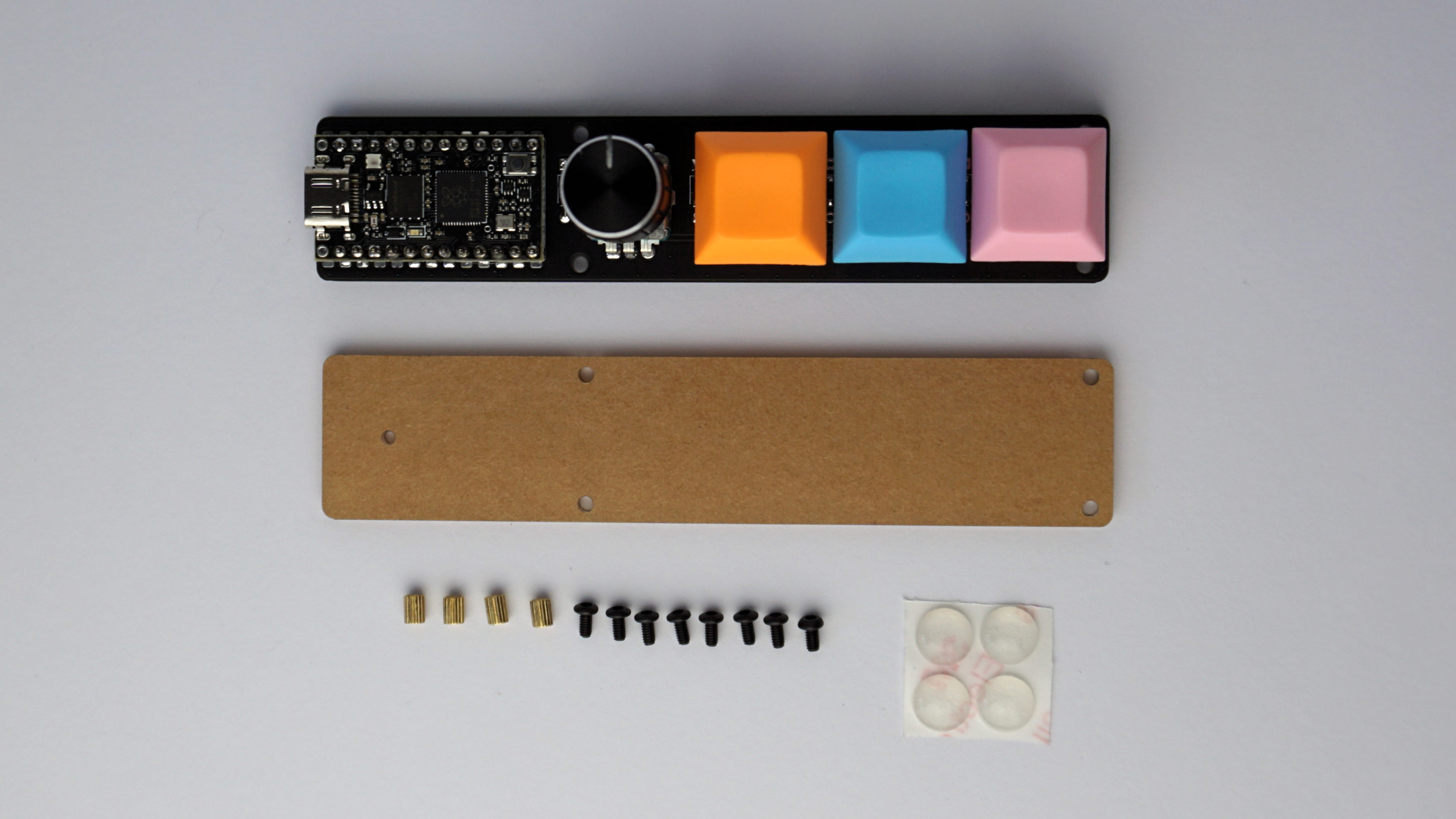
With the electronics done, it’s time to assemble the case. Check you have the below before continuing.
- 1 x Acrylic base
- 4 x M2 standoffs
- 8 x M2 bolts
- 4 x Bumpons
Start by removing the protective paper off the acrylic base. 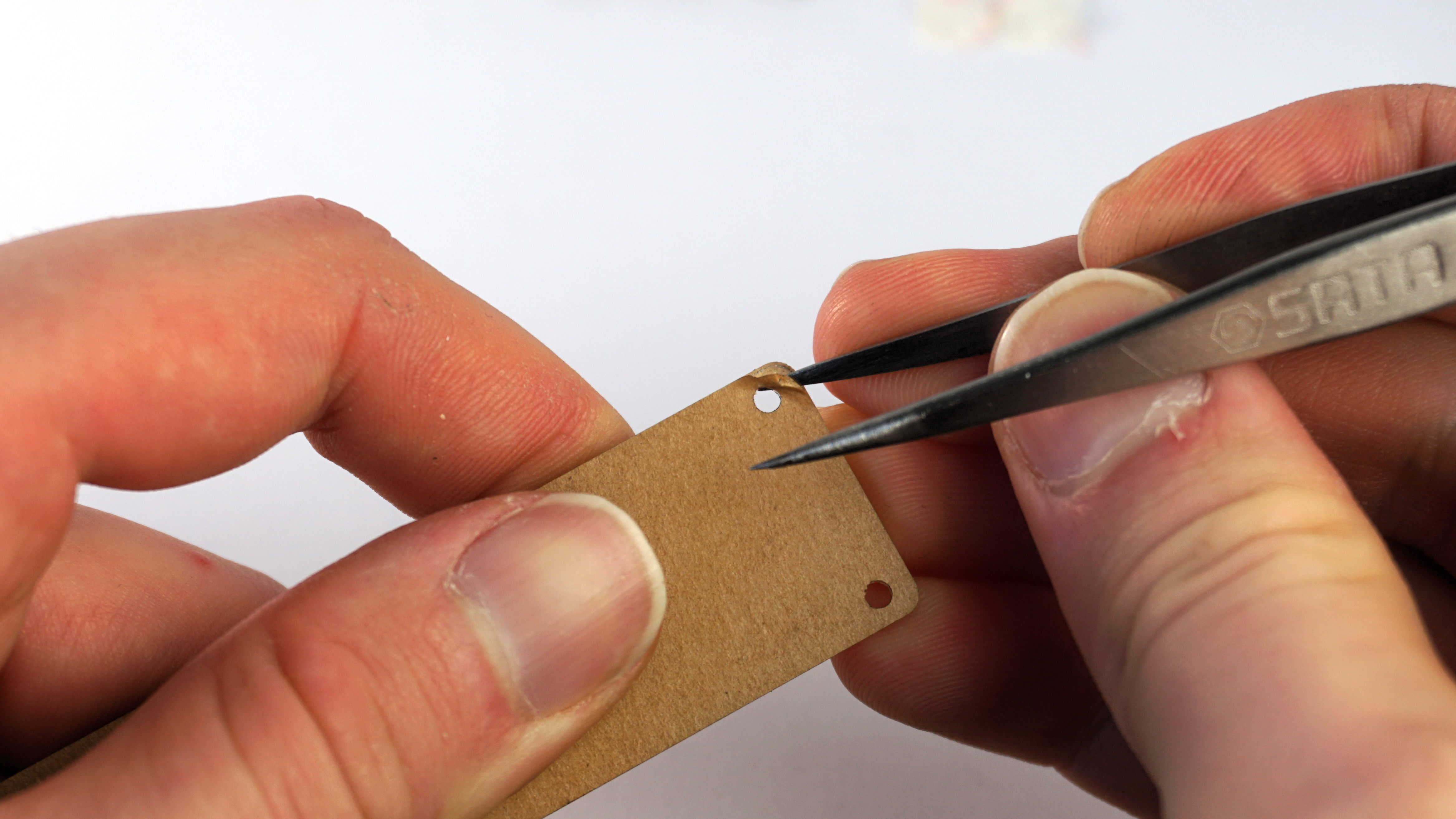
Grab a screw and standoff, and screw into one of the holes in the acrylic. 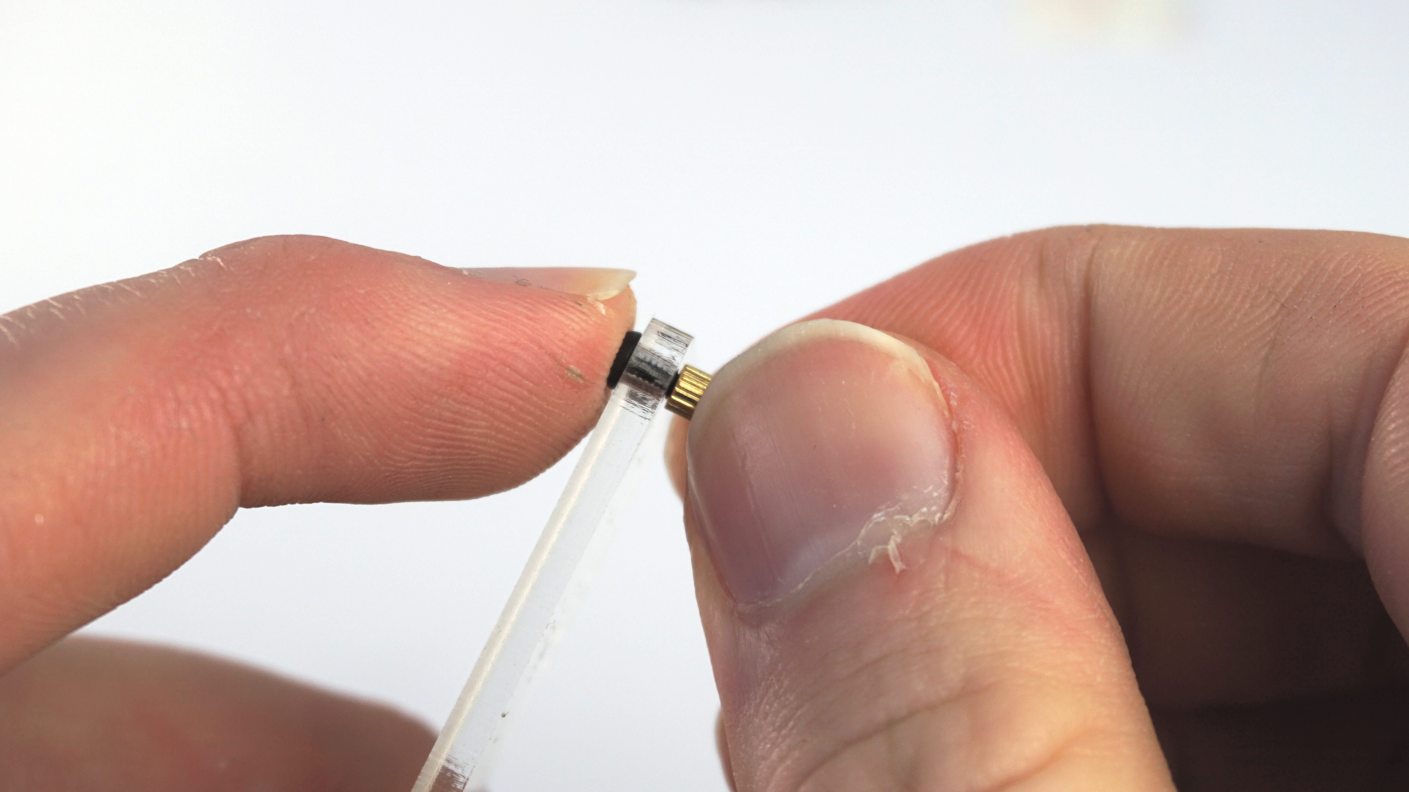
Repeat for all four corners. 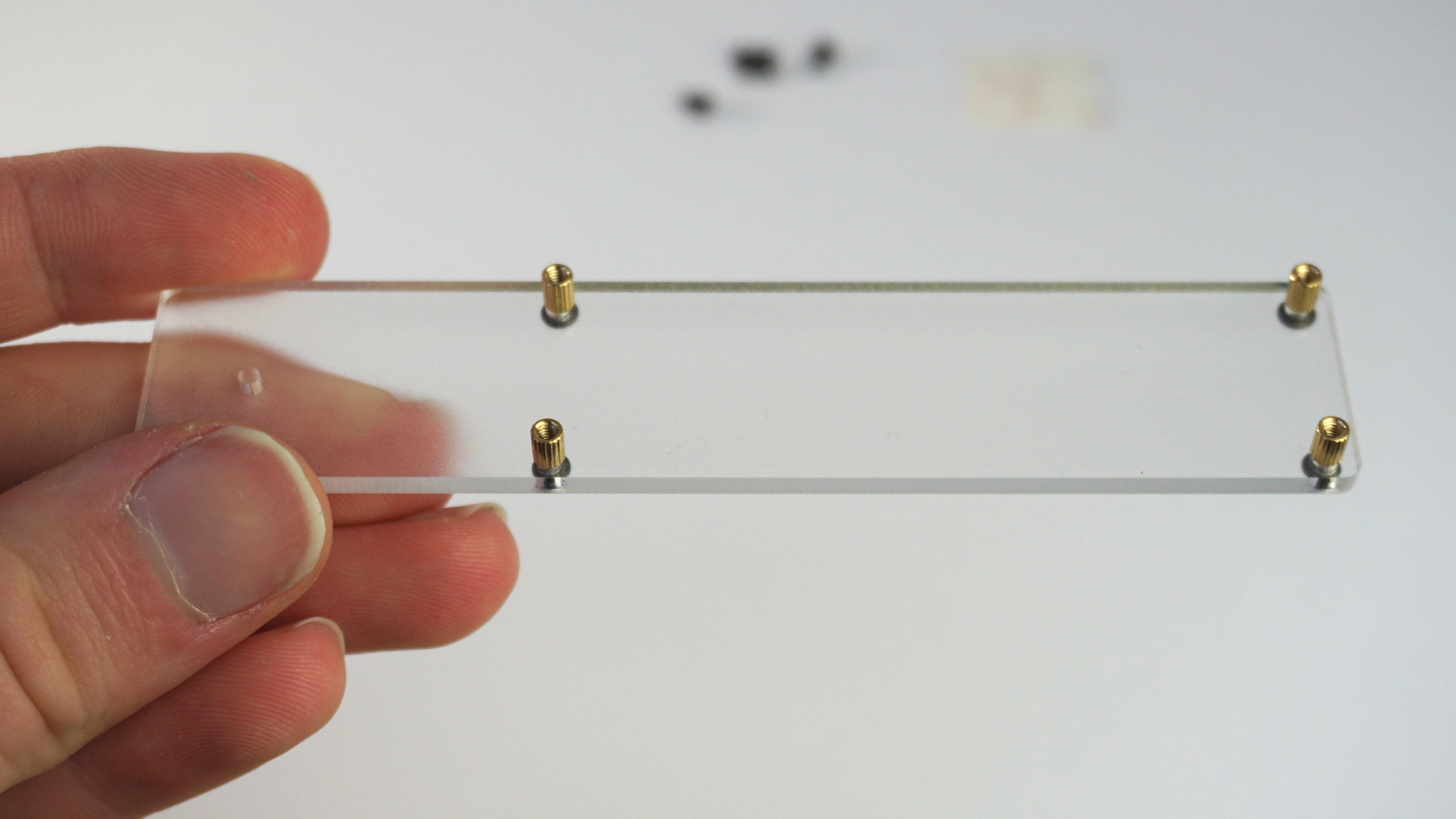
Using a 1.5mm allen key, screw the PCB to the standoffs with the remaining screws. 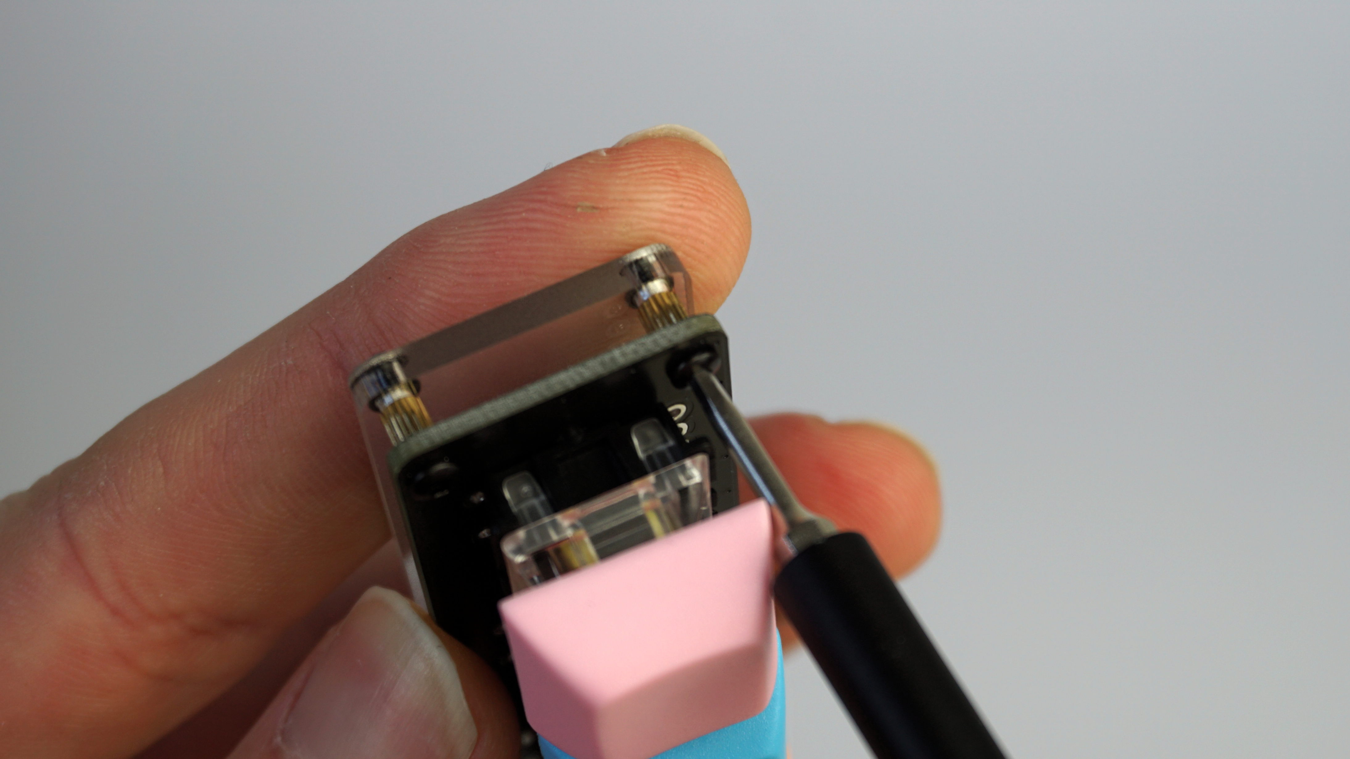
Finally, add the bumpons to four corners of the acrylic. 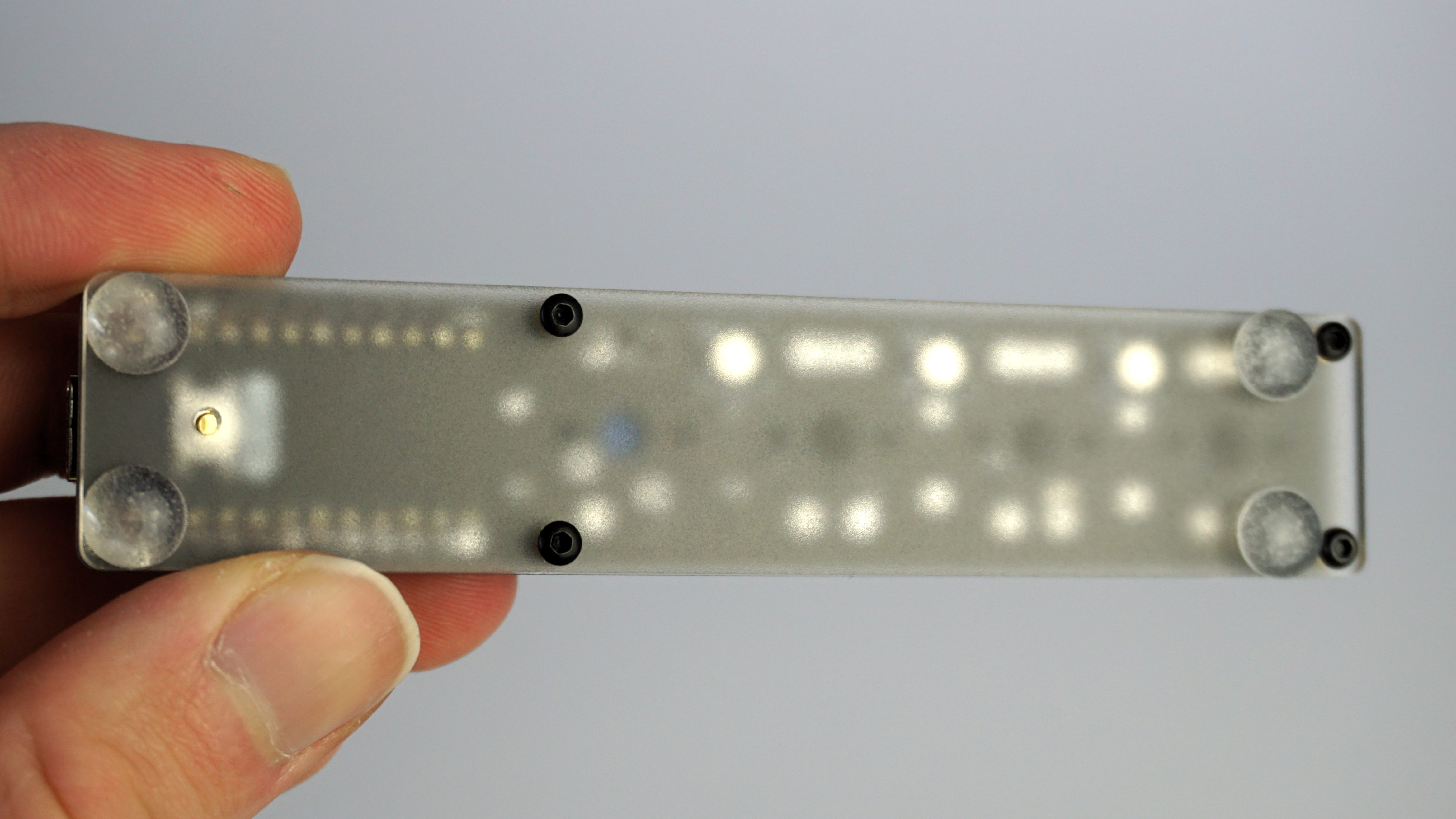
Now it’s time to sit back and enjoy all of your hard work, as you’ve successfully assembled your new keyboard and can begin programming it.
The End
With all the above done, you should have a fully functioning keyboard whose function is only limited by your imagination (and the rules of physics). If you would like to learn more, the KiCad design files for the PCB can be found on Github, and the schematic can be downloaded here.
Caught the soldering bug and want to buy some equipment for use at home? I have a suggested list here.
If you have any questions or feedback please let me know, otherwise happy typing!