On your bPod, you’ll find a tools menu which provides a way to interface with a number of common embedded protocols. The digital explorer board in combination with a logic analyser provides a way to see what these signals look like, and hopefully provide a greater understanding of the protocols used in modern electronics.
Setup
Connecting the Digital Explorer Board
Connecting the Digital Explorer Board is as simple as plugging it into a 5V power source, preferably your laptop so you can modify the code. Once connected to your laptop, it’ll show up as a mass storage device CIRCUITPY and by opening the code.py file found within you can modify the code running on it. The code is all written in Python and when saved is automatically run - all on device!
To see the output from your code, use a serial monitor tool (e.g. Putty for Windows, screen for Linux) to connect to the COM or dev/ttyACM port that enumerates when the device is plugged in. For more info, check out the CircuitPython docs.
Connecting the Logic Analyser
Before connecting the logic analyser, we need to install Pulseview, an open source logic analyser tool.
Sparkfun has a great document on how to setup the software to work with your logic analyser.
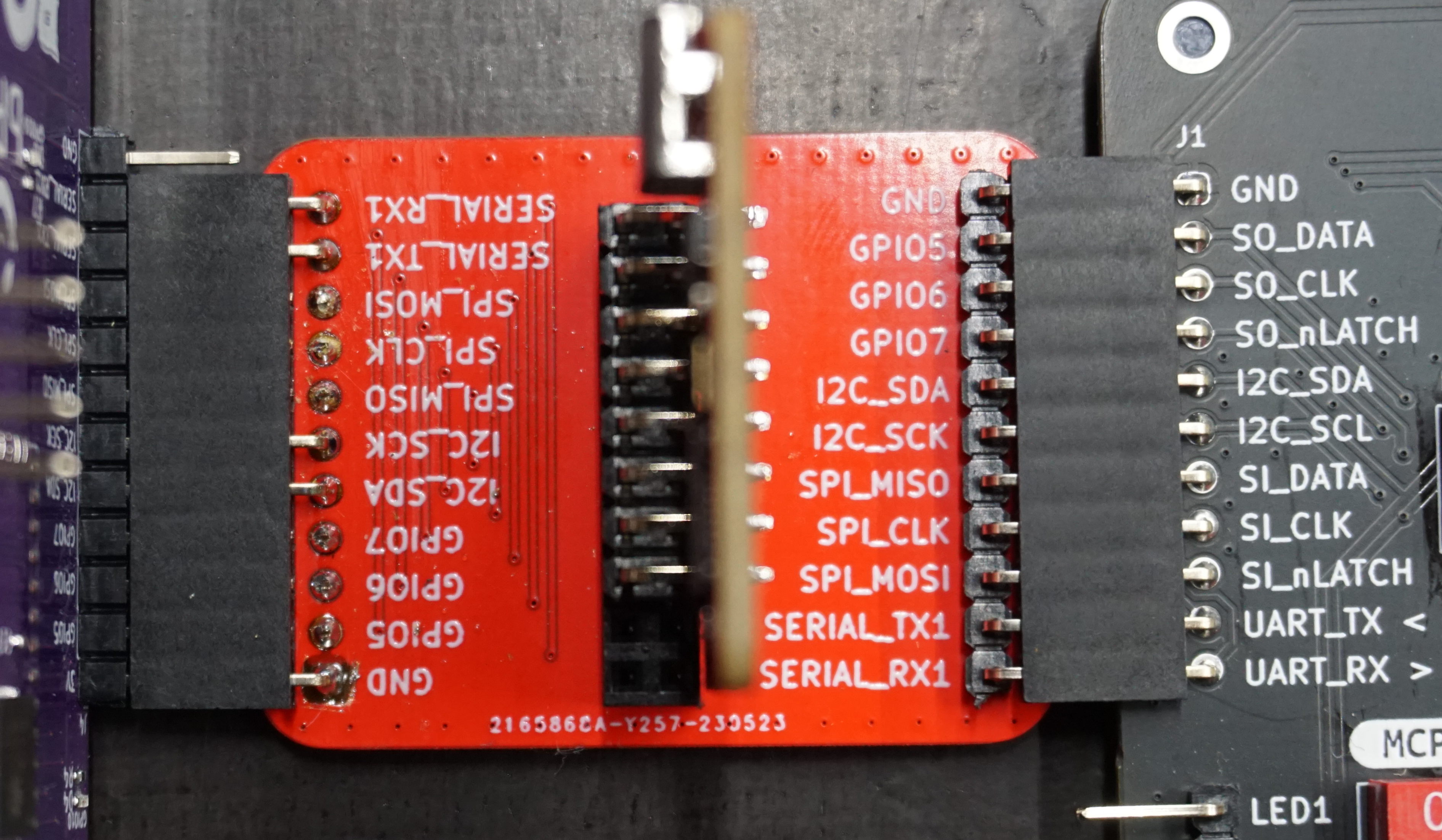
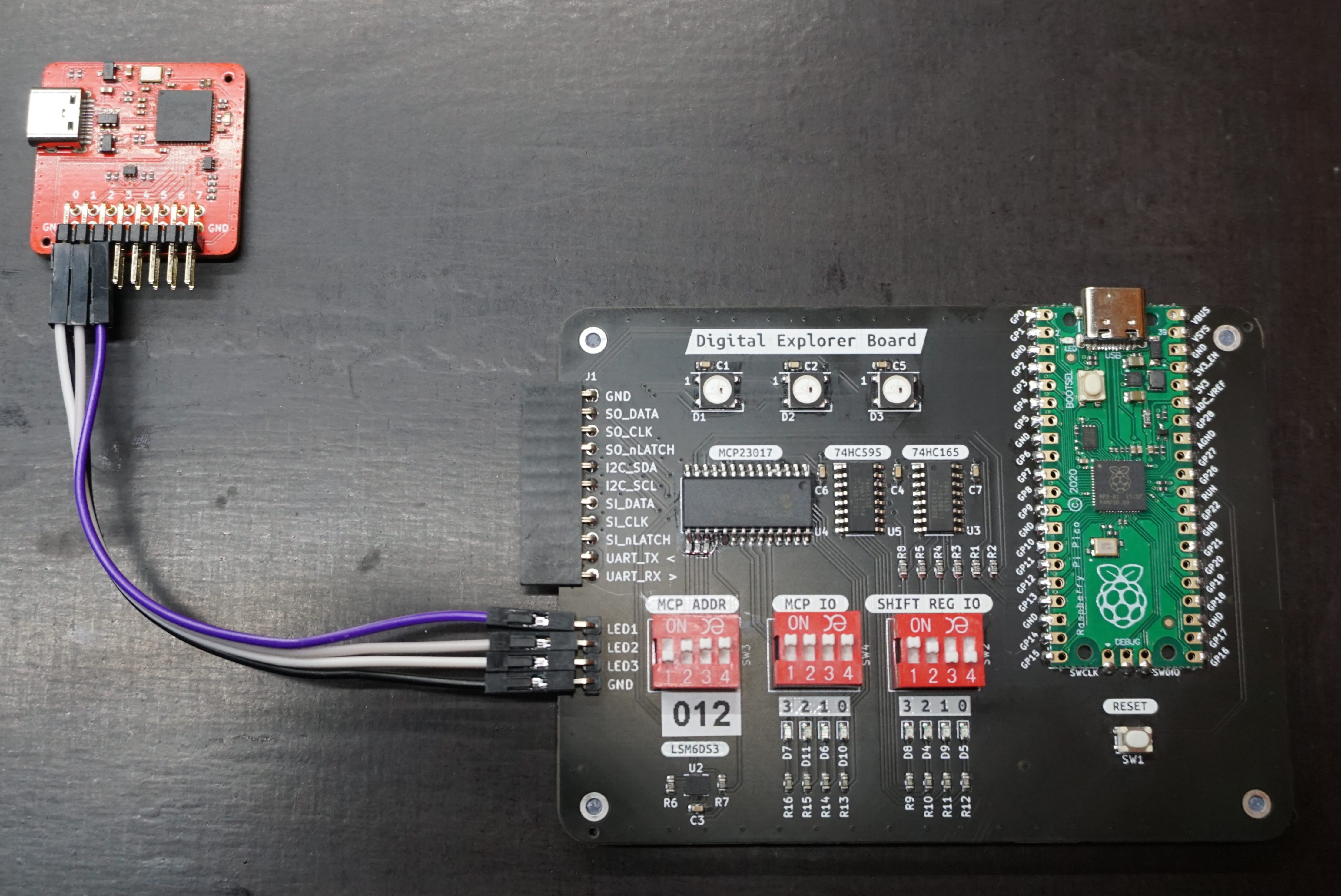
To connect the logic analyser to the Digital Explorer Board, we need to plug in the interceptor board, which acts as a passthrough between bPod and the Digital Explorer Board, whilst providing a pinout to plug the logic analyser into. When connecting the logic analyser, ensure the USB port is pointing in the same direction as the port on the Digital Explorer Board, as otherwise smoke may escape from your PC!
Ensure you set the sample rate to at least 1MHz, otherwise the sample speed will be too slow to detect some of the signals!
Connecting bPod
bPod plugs into the interceptor board upside down, as shown in the below image. You’ll notice the interceptor board has one fewer pin than bPod, this is to prevent smoke if plugged in the wrong way.
For reasons I can’t tell you (cough cough CTF) plugging bPod into the board will cause I2C issues with the MCP23017, so you’ll need to comment that code out (or put the RP2040 into bootloader by holding the BOOT button on the Pico and pressing the reset button) depending on what you want to do.
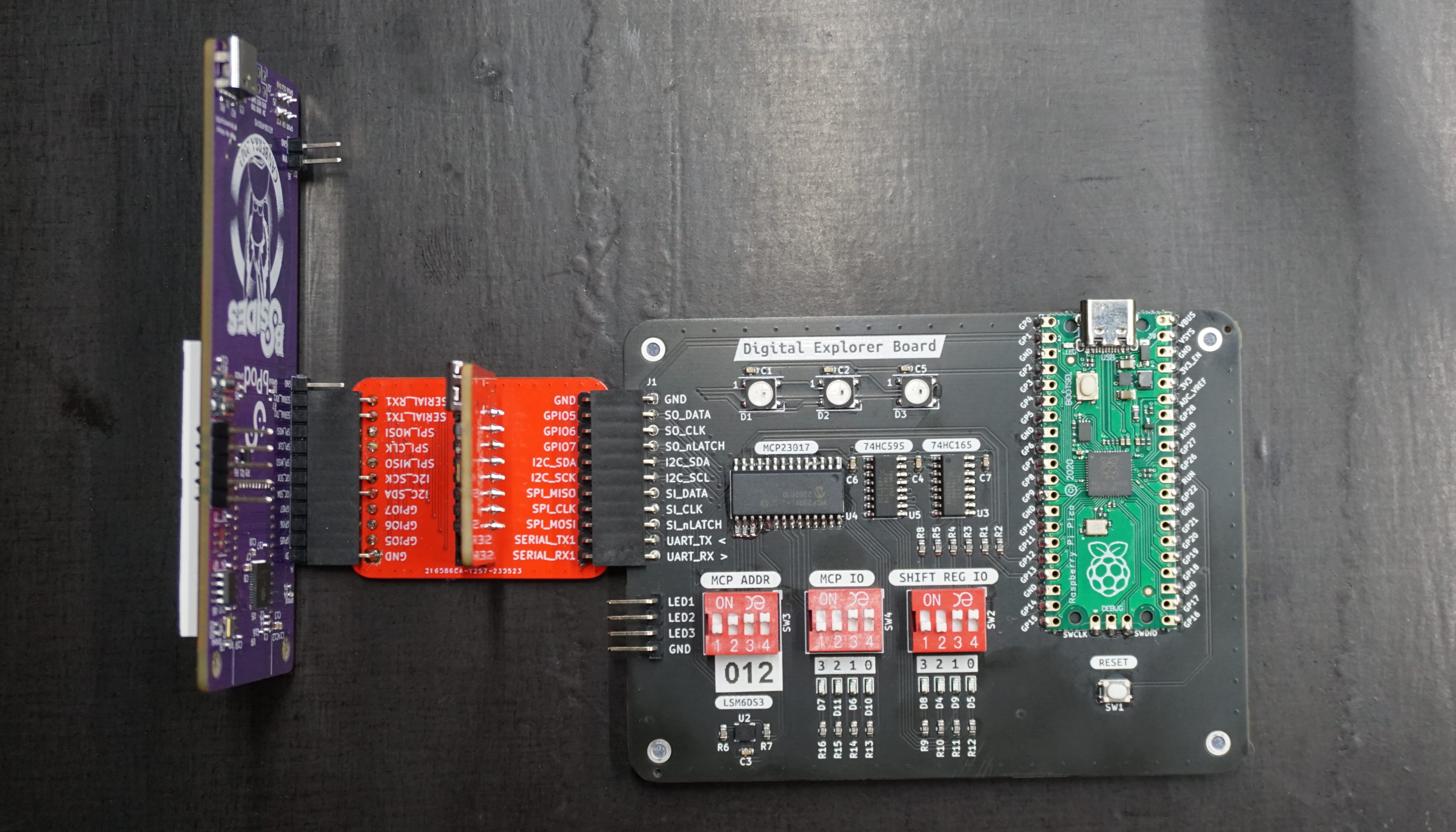
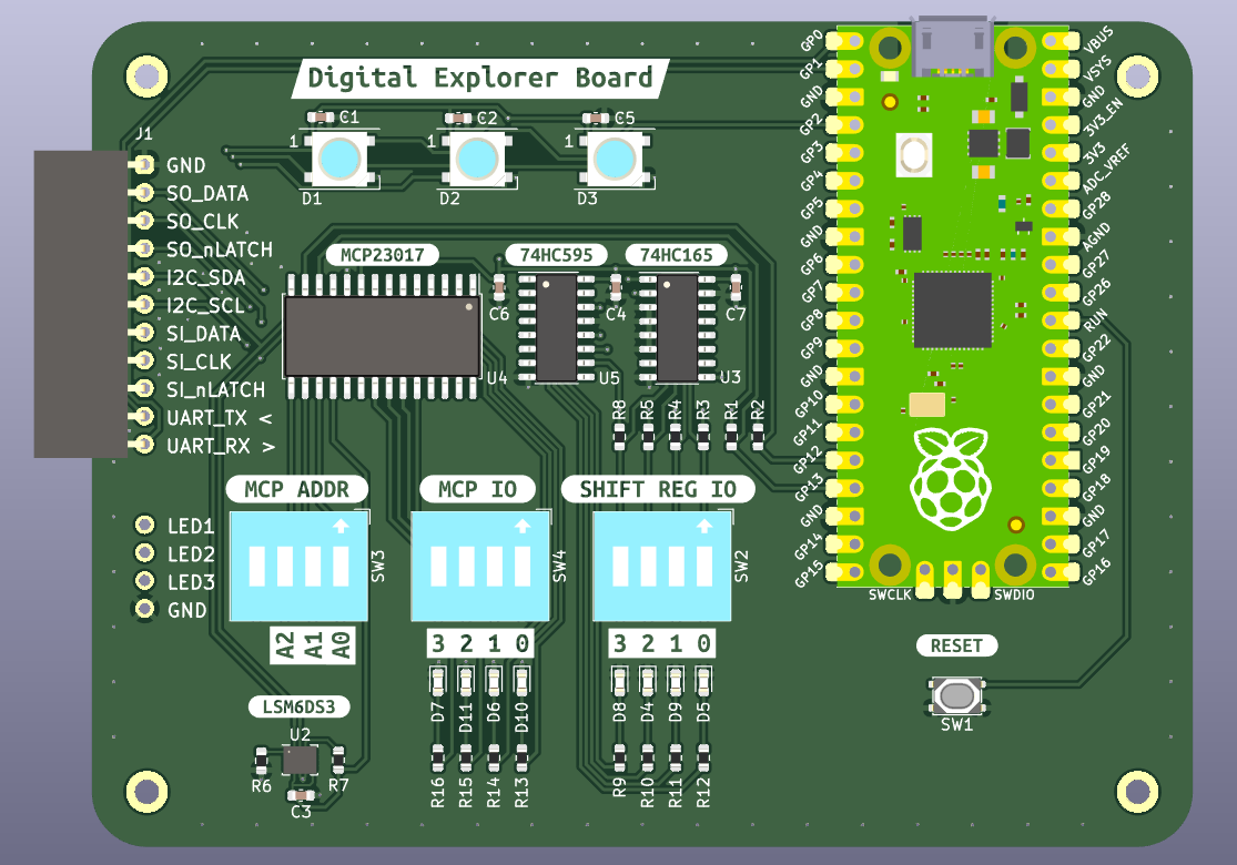
Tour of the Digital Explorer Board
The digital explorer board contains a number of common ICs found in modern electronics. They are summarised below:
| Part Number | Type | Comms Protocol | Datasheet | |
|---|---|---|---|---|
| 74HC595 | 8-Bit Shift Registers With 3-State Output Registers | SPI | https://www.ti.com/lit/ds/symlink/sn74hc595.pdf | |
| 74HC165 | 8-Bit Parallel-Load Shift Registers | SPI | https://www.ti.com/lit/ds/symlink/sn74hc165.pdf | |
| MCP23017 | 16-Bit I/O Expander with Serial Interface | I2C | https://ww1.microchip.com/downloads/aemDocuments/documents/APID/ProductDocuments/DataSheets/MCP23017-Data-Sheet-DS20001952.pdf | |
| LSM6DS3 | Inertial Module: 3D Accelerometer and 3D Gyroscope | I2C | https://www.st.com/resource/en/datasheet/lsm6ds3tr-c.pdf | |
| WS2812B | Addressable LED | Proprietary | https://cdn-shop.adafruit.com/datasheets/WS2812B.pdf |
The board also has a number of DIP switches and LEDs to interact with:
- MCP ADDR is used to set the I2C address of the MCP23017 from 0x20 to 0x27.
- MCP IO is connected to 4 input pins on the MCP23017, and the state of these DIP switches is mirrored to the LEDs below.
- SHIFT REG IO is connected to the 74HC165, and the corresponding LEDs are connected to the 74HC595.
- WS2812 LEDs are located at the top of the board, and display pretty colours. The data signal going into each LED is broken out below the bPod connector.
The board also breaks out a UART from the RP2040 the bPod connector. For more info on how this is all connected check out the schematic.
What is SPI / I2C / UART?
Much like on the digital explorer board, a typical printed circuit board assembly will consist of a microcontroller as the brains of the operation, and a number of peripherals to perform specific tasks which the microcontroller cannot. To interface between the micro and peripheral, a number of standardised communication interfaces exist to allow part from varying manufactures to exist together.
These days most microcontrollers operate at 3.3V, and as such a logic 1 is when the voltage at the pin is 3.3V, and a logic 0 when the voltage is zero.
SPI - Serial Peripheral Interface
SPI is one of the most common interfaces, and is typically configured in a controller / peripheral (master / slave) configuration with the following pins:
- SCLK Serial Clock (driven from controller)
- COPI Controller Out Peripheral In (data output from controller)
- CIPO Peripheral Out Controller In (data output from peripheral)
- nCS Chip Select (active low signal to begin transmission)
SPI is a simple interface which allows high data throughput, making it a great option for both simple devices like shift registers, all the way to SD cards and TFT displays.
Sparkfun has a great document going into all the details about SPI.
I2C - Inter-Integrated Circuit
I2C is also another common interface, and is unique in that you can connect 127 devices together using only two pins.
- SDA Serial Data
- SCL Serial Clock
Due to having multiple devices on a shared bus each device has an address, and the controller needs to send the device address before sending data or a command. This greatly reduces the data throughput for a device on I2C, but for slow changing signals (e.g. LEDs, temperature) it’s a great solution as it does not require a high pin count from the microcontroller.
Once again, Sparkfun goes into great detail about the inner workings of I2C.
UART - Universal Asynchronous Receiver-Transmitter
If you’ve ever plugged in a cable and opened a terminal to an embedded device, you were most likely using UART to communicate with the device. It’s commonly used for communication between two microcontrollers, or between human and microcontroller.
- TX Transmit (leaving micro)
- RX Receive (entering micro)
As UART is asynchronous, both devices need to be configured to the correct baudrate (bits per second) along with length, stop, and parity bits. There are two common speeds (9600 and 115200) and the so called “8N1” (8 bits, no parity, one stop) configuration which are used by most devices.
You can probably guess what this link is if you’d like to learn more about UART.
WS2812B - Individually Addressable LEDs
Whilst WS2812Bs are not a communication protocol, they are a LED used in many hobby projects as you can have an infinite chain of RGB LEDs controlled by a single microcontroller pin.
It uses a single pin which toggles between high and low, with the time high / time low indicating a 1 or a 0. These 1 and 0’s are formed into a packet containing the R/G/B value for each LED, and sent down the chain to make your PCBs look pretty.
Page 4 of the datasheet goes into more detail about this protocol.
What Does the Board Do?
To demonstrate the above discussed protocols, after configuring the peripherals the the code on the RP2040 talks to each device in a big super loop, enabling you to see how changing the DIP switches / angle of the board impacts the messages being sent over the wires.
Reading 74HC165 Shift Register Values
Do NOT have bPod connected for this demo
With SPI, the below sequence of operation is used to read values.
- Assert chip select (normally low, but for the 74HC165 it’s active high)
- Clock rising edge causes peripheral to shift out data
- Controller reads data that was shifted out
- Clock goes low
- Do it all over again until all data has been read
- Chip select released
The below code shows how this is done on the RP2040
1
2
3
4
5
6
7
8
9
10
11
12
13
14
15
16
17
18
19
20
21
22
23
24
25
26
# Shift in 8 bits from 165 shift register
def shift_in():
    # Var to store read value in
    readback = 0

    # Set chip select high to begin read
    # Normally chip select is active low, but it's not this time
    # I know the name is wrong, but I'm keeping it identical to the schematic / PCB
    si_nlatch.value = True

    # For the 8 inputs on the shift register, read them into the temp var
    for i in range(0, 8):
        # Clock going high triggers shift out of next value
        si_clk.value = True

        # Bitwise or with 0 will set value if set on shift reg
        readback |= (si_data.value) << (7-i)

        # Clock low so we can bring it high next time
        si_clk.value = False

    # Transaction over, return chip select to default state
    si_nlatch.value = False

    # Bitshifting to align values to MSB and invert as DIP switch is active low
    return (readback << 3) ^ 0xFF
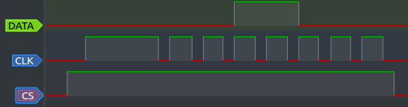
The below trace from Pulseview shows bits 4 and 5 being high, with the rest low.
Writing 74HC595 Shift Register Values
Do NOT have bPod connected for this demo
Writing the above read values out to the 74HC595 is more or less the same, with the change that the controller sets the data pin with the value before setting the clock high.
1
2
3
4
5
6
7
8
9
10
11
12
13
14
15
16
17
18
19
20
21
22
23
24
25
26
# Shift out 8 bit field to 595 shift register
def shift_out(bitfield):
    # Chip enable low to begin transaction
    so_nlatch.value = False

    # For each bit in the bitfield
    for i in range(0, 8):
        # Set clock low
        so_clk.value = False

        # Check if bit is set and set data high / low accordingly
        if bitfield & (1 << i):
            so_data.value = True
        else:
            so_data.value = False

        # Clock going high shift the above set data in
        so_clk.value = True

        # Return data to zero value (not required, but easier for timing)
        so_data.value = False

    # Ensure clock is low when transaction finished
    so_clk.value = False
    # Chif enable high now transaction is done
    so_nlatch.value = True
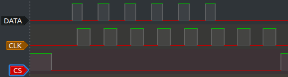
You can see the below has six outputs high and two low, which maps to the bitshifted value we got back from the 165 input read. The reason for the bits not lining up exactly is that the pins were swapped to make PCB routing easier, and the alignment is handled in software.
Reading and Writing MCP32017 GPIO Expander Values
Do NOT have bPod connected for this demo
I2C takes more than a dozen lines of code to control, so I’ve used the CircuitPython busio library for this example. It does however make the demo a bit more complicated than I’d like due to how it handles the IO.
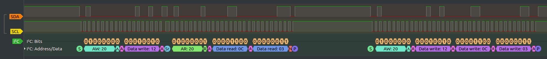
The logic trace shows the below.
- Setup Address Write to
0x20(MCP Address) - Tell MCP we want to read read register
0x120x12is the GPIOA register, which stores the state for the IO pins
- Setup read to MCP
- Read two bytes (
0x0C, 0x03)- It appears the default library reads both ports at once, as the second byte (addr
0x13is for GPIOB)
- It appears the default library reads both ports at once, as the second byte (addr
- Setup write to MCP
Write two bytes at
0x12(i.e. write the values out to the MCP)- Interspersed between all of this are ACKs and NAKs which are used to confirm the peripheral has received the instruction and will act upon it (or not!).
Reading LSM6DS3 Accelerometer Values
Do NOT have bPod connected for this demo
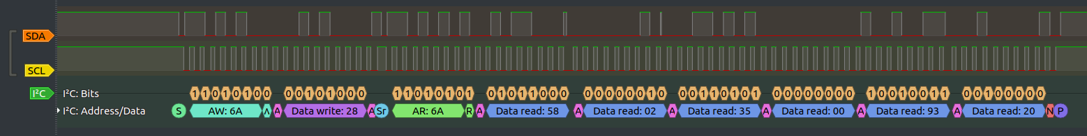
By comparison to the MCP23017, the LSM6DS3 I2C read is a lot more straightforward.
- Talking to chip address
0x6A(LSM), read address0x28(OUT_X_L_XL). - Taking to LSM, read 6 bytes from above address.
- Each X, Y, Z value is 16 bits (two bytes), so reading 6 bytes will read out all the data at once.
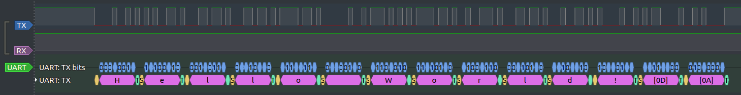
Writing Data Stream Over UART
Connect bPod for this demo, however you’ll have to comment out all the MCP23017 code otherwise it won’t run (lines 24-57, 179-182)
Connect your bPod, and navigate to the Tools -> uartterm page. With the setting of 115200/8N1, select Terminal.
You should now see Hello World! being printed on the screen.
From the logic analyser, you should also be able to decode this message.
Controlling MCP23017 from bPod
Connect bPod for this demo, however you’ll have to comment out all the MCP23017 code otherwise it won’t run (lines 24-57, 179-182)
bPod has the ability to control the MCP23017 IO expander just like we do on the digital explorer board.
- Go to tools, and run
i2csniffto check the address of your MCP23017. I’ll be in the range of0x20 - 0x27. - Then go to the
MCP23017tab, set the address to the above. - Toggle
IOB0 - IOB3, and you should see the LEDs toggle on and off.
Controlling WS2812B Addressable LEDs
Do NOT have bPod connected for this demo
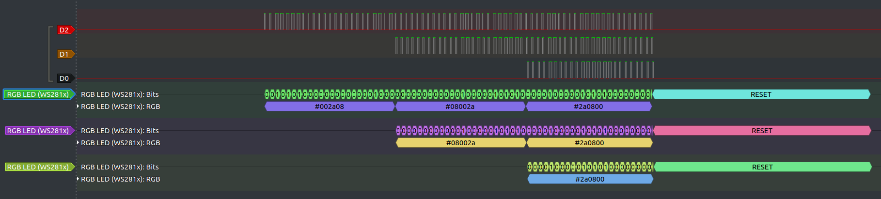
WS2812B’s take a serial stream of packets into the first LED, and pass on packets 2…n to the next LED. This can be seen in the below stream, where three bytes make it to the first LED, two to the second LED, and one to the third (last) LED in the stream.